175
D PF L T
S
D
1
2
M
3
○○○○
FNC
49
X Y M S
D.b R.b
KnX KnY
KnM KnS
T C
D,R
V,Z
UnG
K,H
E
" $"
S
D
S : the source data to be converted
D : the destination device to store the equivalent
float format value
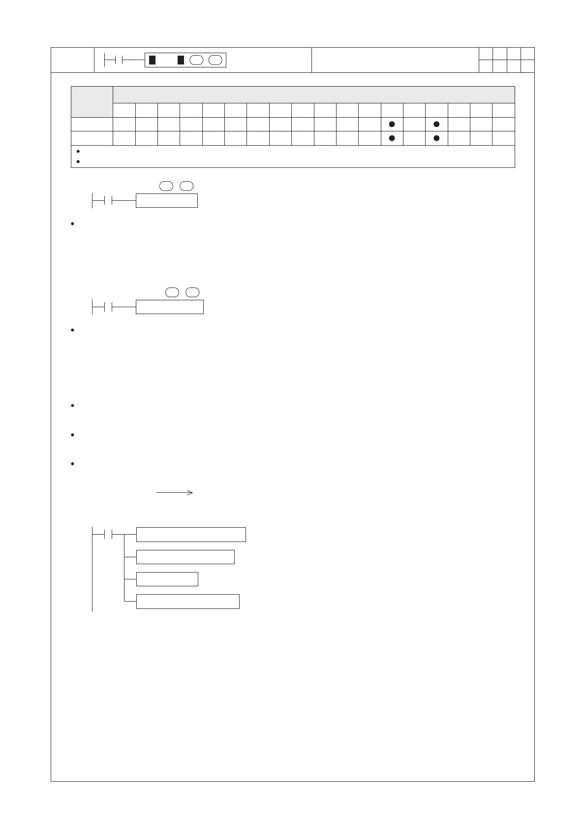
When X0=“ON”, it performs the convert operation from the content value of 16 bits register D0 (which is a BIN
integer) to a binary floating point number, and the converted result is copied to the destination devices (D11, D10).
When X1=“ON”, it performs the convert operation from the content value of 32 bits registers (D2,D3) (which is a
BIN integer) to a binary floating point number, and the converted result is copied to the destination devices (D13,
D12).
DFLT D2 D12
X1
2 × 3.14 ×( D0 ) ( D11, D10 )
DEDIV K314 K100 D20
DEMUL K2 D20 D22
FLT D0 D24
DEMUL D22 D24 D10
M9000
FLT D0 D10
X0
S
D
S
D
Operand
Devices
BIN Integer → Binary Floating Point
Format
The 16-bit instruction, S occupies 1 and D occupies 2 components
The 32-bit instruction, S occupies 2 and D occupies 2 components
There is not required to use this instruction to convert a constant K or H at a oating calculation, because the constant
will convert to binary oating point format automatically when the oating calculation is in operation.
A oating point number in the system should occupy two consecutive registers, for the storage format of a oating
point number in registers, please refere to the section 2-13 “Numerical System”.
BIN integer
Binary floating point
format number
3.14 → (D21,D20) Binary floating point format number
2×3.14 → (D23,D22) Binary floating point format number
(D0) BIN integer → (D25,D24) Binary floating point format number
2×3.14×(D0) → (D11,D10) Binary floating point format number
Floating point calculation example:
Use the PLC instruction to calculate the result of circumference
 Loading...