376
1
2
M
3
○○○○
FNC
89
L N K
I
S1
S2
n
X Y M S
D.b R.b
KnX KnY
KnM KnS
T C
D,R
V,Z
UnG
K,H
E
" $"
S1
S2
n
LI NK CP1_DATA_TRANS D100 K1
X20
S2S 1
n
S1
■
M9104
■
M9114
■
M9124
■
M9134
■
M9144
M9143
M9103
M9113
M9123
M9133
VS series
PLC
RS- 485RS- 232
Operand
Devices
Easy Link Communication Instruction
Using a Table Code Q0~Q31 (V, Z index modiable) or a Table Nickname (by user-dened 16 English characters)
For the VS1 series, n = 1~2; for the VS2 or VSM series, n = 1~3; for the VS3 series, n = 1~5
S1 : the communication table that describes the data
receiving and transmitting
S2 : the working area for the instruction that occupies
4 registers
n : to designate the communication port, 1~5=CP1~CP5
The VS Series PLC uses this instruction to transmit or get the designated data via its Communication Port CP1~
CP5 with other VS PLCs.
The CP1~CP5 are multi-functional communication ports. Each port can choose an appropriate communication
type from its various functions. When this instruction is using a port, should choose the “Application type:”
become the “VS Computer Link Master”. Regarding the application type selection and related parameter setting,
please specify it from the programming software Ladder Master S and at the “Project” -- “COM Port Setting”.
This instruction could be used to transfer for various devices that is including all the Y, M, S, T, C, D and R (except
for special M and special D).
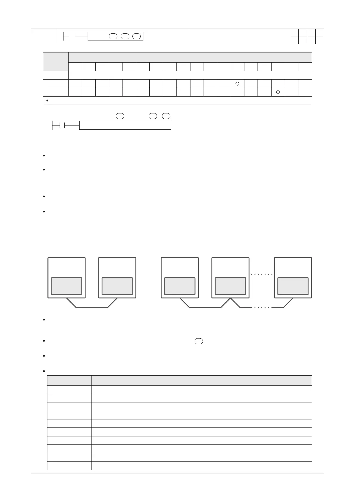
As shown in the gure below, select one of these linked PLCs as the Master station and the rest as the Slave
stations. First, use the Ladder Master S to orderly open every Slave PLC's project and set its “Application type:” as
the “VS Computer Link Slave” then to set an unique station No. (ranging from 0~254). After that, connect to the
programming port of every PLC to load the project to each Slave PLC.
Next, write this instruction in the Master PLC's program and set its “Application type:” as the “VS Computer Link
Master”, then edit the LINK communication table to designate data transferring actions. After that, to load this
project to the Master PLC. Following these procedures, the purpose of data delivery between the PLCs can be
reached.
VS series
PLC
VS series
PLC
VS series
PLC
VS series
PLC
VS LINK
Master
VS LINK
Slave
VS LINK
Master
VS LINK
Slave
VS LINK
Slave
When X20=“ON”, the LINK instruction starts execution. According to the contents described in the
“CP1_DATA_TRANS” communication table, it proceeds data write or read actions to the appointed Slave PLC
stations, while the D100~D103 will be occupied to store the state of instruction execution.
When the contents of the communication table specied by the are execution completed from beginning to end,
the M9104 will be “ON” for a scan time then the procedure will start over again from the rst item set of the table.
When the X20 turns from “ON” to “OFF”, this instruction stops and the data sharing immediately stop but data
which has transferred previously will still remain.
■
The related special devices are summarized below: ( : Means read only.)
Description
Relay ID No.
CP1 RS / LINK / MBUS instruction on communication abnormal ag.
CP1 LINK / MBUS instruction on execution table complete once ag.
CP2 RS / LINK / MBUS instruction on communication abnormal ag.
CP2 LINK / MBUS instruction on execution table complete once ag.
CP3 RS / LINK / MBUS instruction on communication abnormal ag.
CP3 LINK / MBUS instruction on execution table complete once ag.
CP4 RS / LINK / MBUS instruction on communication abnormal ag.
CP4 LINK / MBUS instruction on execution table complete once ag.
CP5 RS / LINK / MBUS instruction on communication abnormal ag.
CP5 LINK / MBUS instruction on execution table complete once ag.
 Loading...