396
③ Edit the project of VS PLC #2
VS1-32M R
X0 1 2
3 4
5
6 7
10
21 22
23
RUN
ERR
Y0 1 2
3 4
5
6 7
10
11 12
13
PWR
20
11 12
13
14
15 16
17
DC2 4V
INP UT
STOP
MC
RUN
VSPC-200A
USB
Ladder Master S
MOV K4X0 D20
MOV D10 K4Y0
M9000
② Edit the project of VS PLC #1
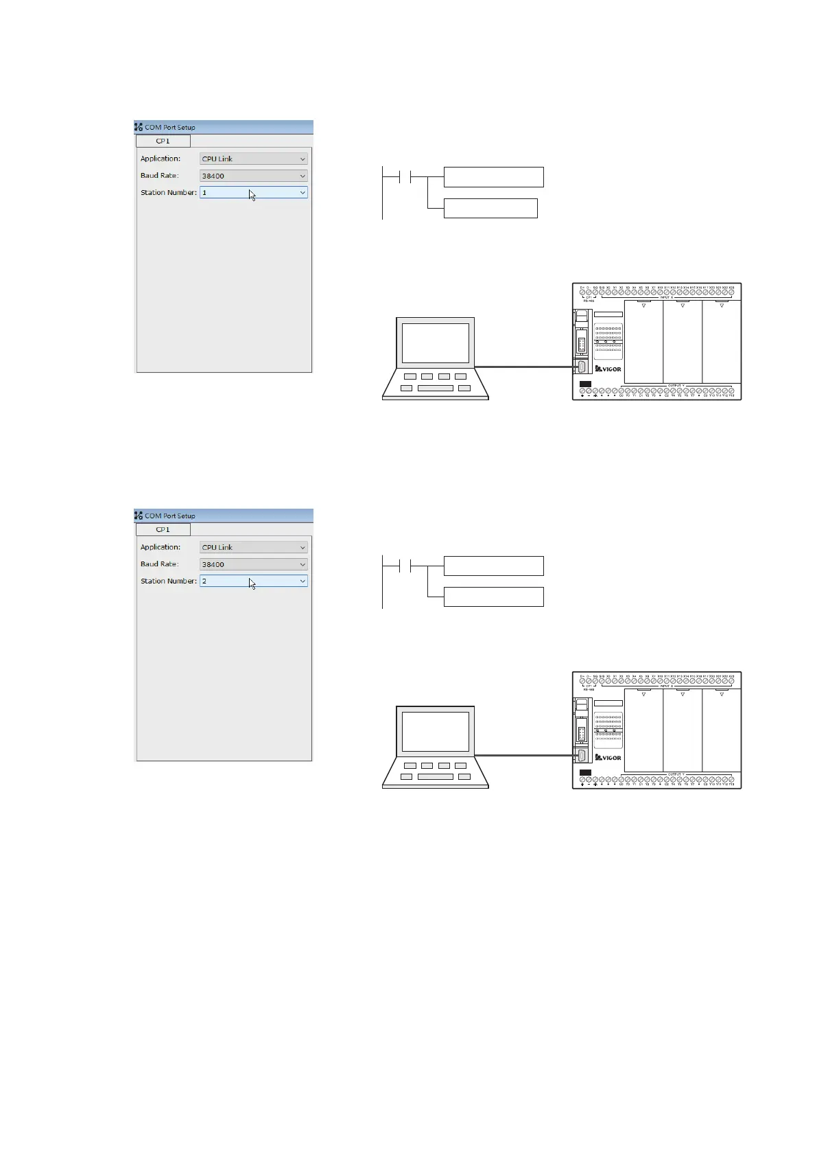
Set the station No.:
Station #1
The program writes to the VS PLC #1.
By the USB programming port, the project is written into the
VS PLC #1
VS PLC #1
VS1-32M R
X0 1 2
3 4
5
6 7
10
21 22
23
RUN
ERR
Y0 1 2
3 4
5
6 7
10
11 12
13
PWR
20
11 12
13
14
15 16
17
DC2 4V
INP UT
STOP
MC
RUN
VSPC-200A
USB
Ladder Master S
Send the status of X0~X17
to the D10.
Send the content value of D0 to the
output points Y0~Y17.
MOV K4X0 D10
MOV D0 K4Y0
M9000
⑤ When the example is performing, the data at every PLC will follow its own program and the communication table to
execute the operation below.
④ After sequentially edit and load the projects to those PLC’s, do the wiring jobs between three PLC’s. Then, trigger
the inputs and monitor the response at the other PLC’s.
Use the Ladder Master S to set the CP1's parameters of VS PLC #1 and compile relevant program. Then, connect
to the USB programming port of VS PLC #1 and write the project into the PLC.
Use the Ladder Master S to set the CP1's parameters of VS PLC #2 and compile relevant program. Then, connect
to the USB programming port of VS PLC #2 and write the project into the PLC.
The program writes to the VS PLC #2.
Send the status of X0~X17
to the D20.
Send the content value of D10 to the
output points Y0~Y17.
By the USB programming port, the project is written into the
VS PLC #2
VS PLC #2
Set the station No.:
Station #2
VS PLC #0: its statuses X0~X17 send to the D0, and the content value of D20 sends to the output points Y0~Y17.
VS PLC #1: its statuses X0~X17 send to the D10, and the content value of D0 sends to the output points Y0~Y17.
VS PLC #2: its statuses X0~X17 send to the D20, and the content value of D10 sends to the output points Y0~Y17.
By the CPU Link communication, the CPUL instruction and its table at the VS PLC #0 that produces the following
results:
The statuses X0~X17 of the VS PLC #0 is reected to the points Y0~Y17 of the VS PLC #1. The statuses X0~X17 of
the VS PLC #1 is reected to the points Y0~Y17 of the VS PLC #2. The statuses X0~X17 of the VS PLC #2 is
reected to the points Y0~Y17 of the VS PLC #0.

 Loading...