X Y M SM T
D.b
V,Z
16-bit
C
S
32-bit
C
R.b
D R
LD
X0Z0 X1Z0
Y0Z0
Y0Z0
MC
(MASTER CONTROL)
MCR
(MC RESET)
END
(END)
NOP
(NO OPERATION)
N0〜 N7
N0〜 N7
MC N0
MCR N0
END
LDP
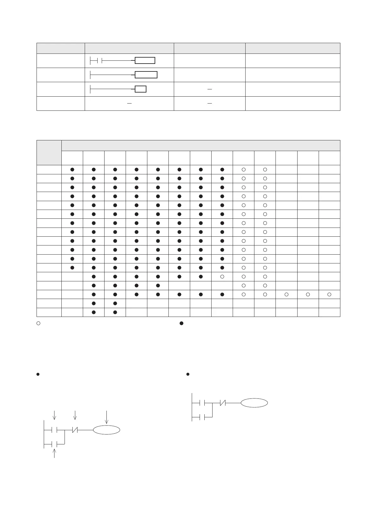
The related device table for the basic instruction
LDI
LDF
AND
ANI
ANDP
ANDF
OR
ORI
ORP
ORF
OUT
SET
RST
PLS
PLF
Means it cannot use the V, Z Index Register to modify Means it could use the V, Z Index Register to modify
To establish the set value of OUT T or OUT C instruction can use the K, D or R, also which can use the Index Register V, Z to
modify.
The basic instructions of the VS series PLC provide the “Bitwise Operation” and the “Bit Index” function. That greatly improving
the convenience of programming, but also greatly enhances the overall performance.
Since a register has 16 bits and they are allocated to
0~F (b0~b15) respectively, the “Bitwise Operation”
function is to treat the individual bit in a register
D or R as a bit component to process, as shown in
the example below:
The “Bit Index” function is to let the bit operand in the basic
instruction has V, Z modifiable capability, as shown in the
example below:
The left diagram shows
the self-holding circuit
about the b15 of D0.
That starts from the b3
of D0 and may release
by the b5 of R1, then
gets a new output to
the b15 of D0.
When the contents of the Z0
is 0, the self-holding circuit
starts from the X0 and may
release by the X1, then gets
a new output to the Y0.
When the contents of the Z0
is 5, the self-holding circuit
starts from the X5 and may
release by the X6, then gets
a new output to the Y5.
R1.5D0.3
D0.F
D0.F
D0's b3 R1's b5 D0's b15
80
Mnemonic Devices Function
Denote the start of a master control block
Denote the end of a master control block
Force the current program scan to end
No operation or null step
Devices
Instru-
ction
Format
D0's b15