Operation2138−1/A1
Winterthur Gas & Diesel Ltd.
2/ 2
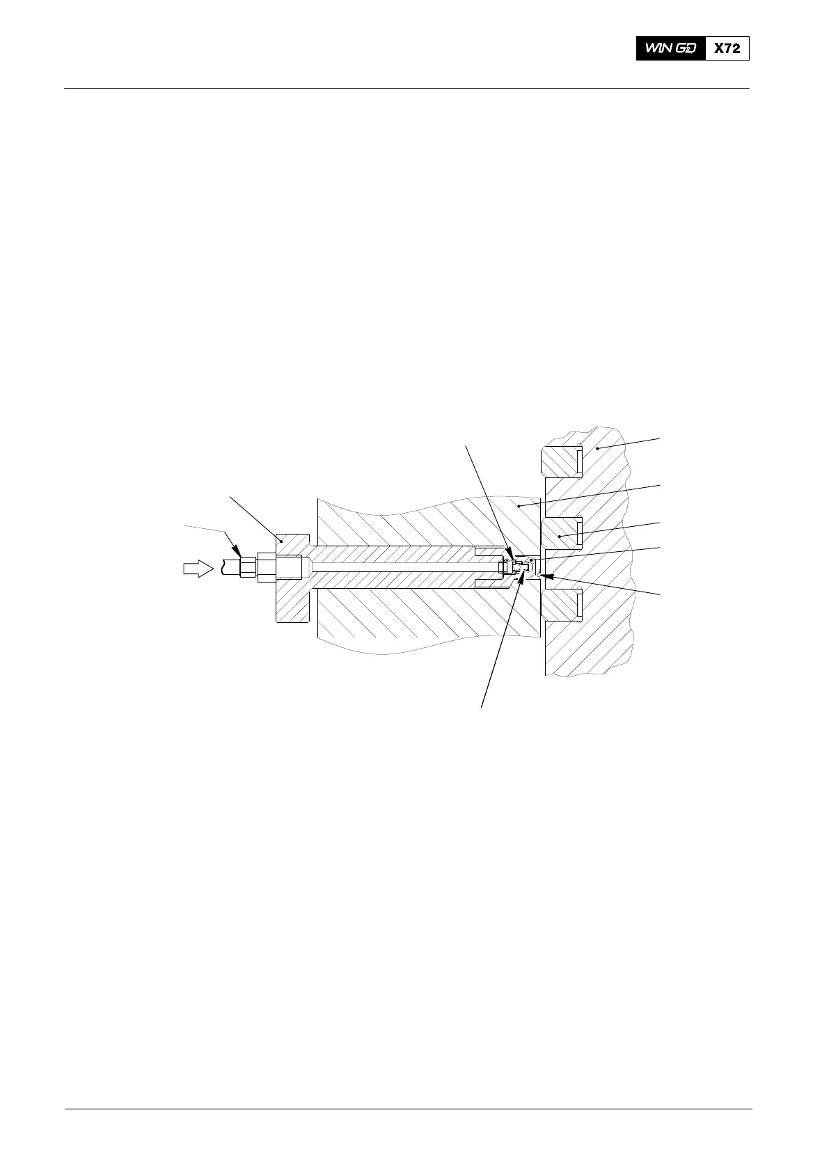
2. Function
The lubricating pump supplies a set quantity of lubricating oil at high pressure through
the connection (OI) into the lubricating quills (see Fig. 2).
The non-return valve (8) opens and the lubricating oil comes out of the the nozzle tip
and the lubricating point (LP) as a spray. The lubricating oil flows equally into the
grooves on the cylinder liner wall (see also 2124−1 Cylinder Liner and 7218−1
Cylinder Lubrication).
After a lubrication pulse, the oil pressure decreases and the force of the compression
spring (3) closes the non-return valve (8).
OI
1
LP
5
6
7
3
8
2
4
WCH01210
Fig. 2: Lubricating Quill
1 Holder 7 Piston
2 Union nut 8 Non-return valve
3 Compression spring
4 Nozzle tip
5 Piston ring LP Lubricating point in cylinder liner
6 Cylinder liner OI Lubricating oil inlet
Lubricating Quills on Cylinder Liner
2014