Operation7722−1/A1
Winterthur Gas & Diesel Ltd.
2/ 5
2. Operation
2.1 Integrated Electrical Balancer
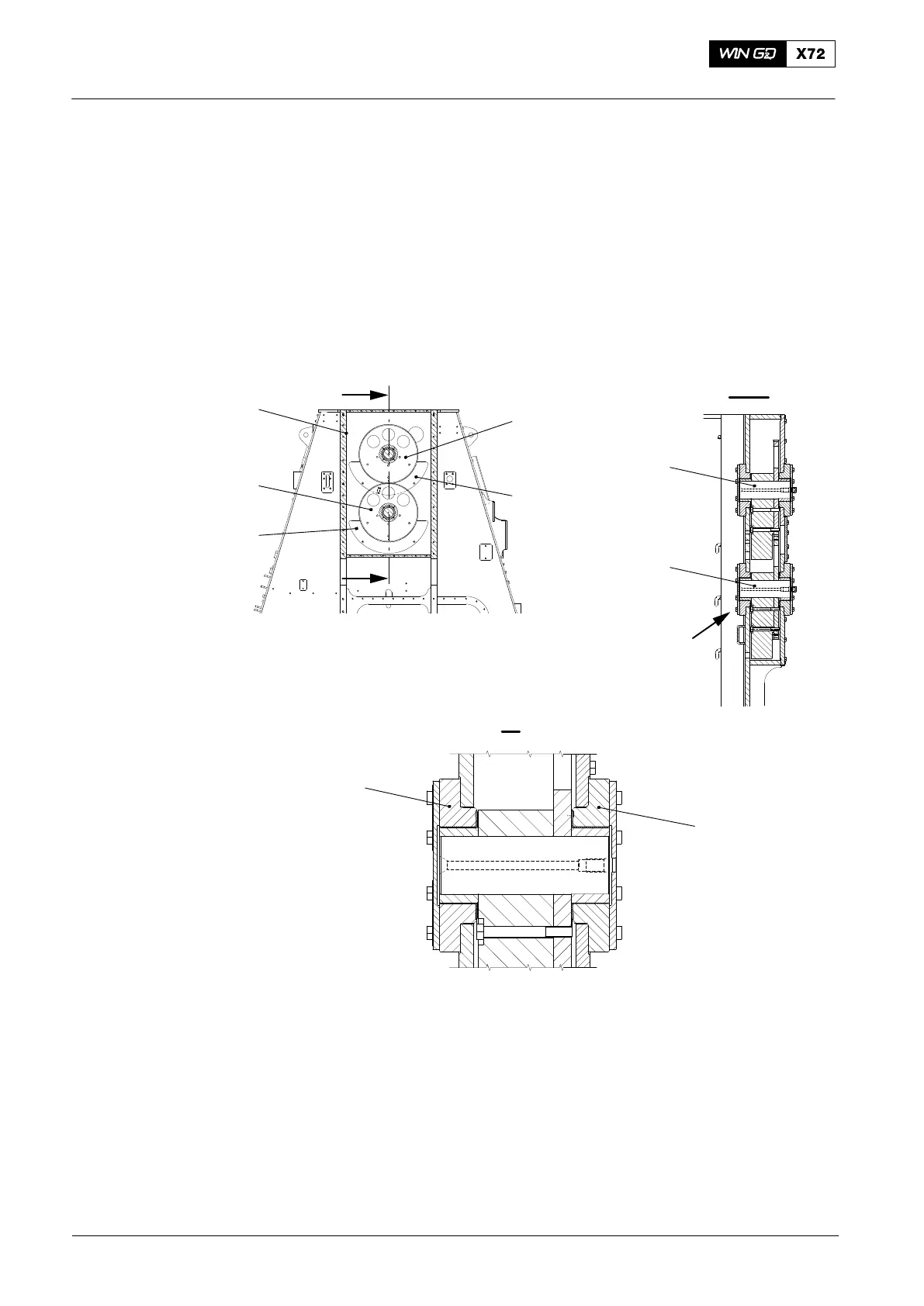
The two shafts (6 and 7, Fig 2) are installed in the housing (5). These shafts turn in
opposite directions at two times the engine speed. When the gear wheels (1, 4) turn,
the two balance weights (2, 3) cancel each effect of the horizontal centrifugal forces.
A vertical force moves up and down two times for each revolution of the engine.
Each of the two shafts transmit the balance forces through the bearings (8, 9).
9
I
I
6
7
I
I
2
4
3
5
I - I
WCH03085
1
8
Fig. 2: Electrical Balancer and Shafts
1 Gear wheel 6 Shaft
2 Balance weight 7 Shaft
3 Balance weight 8 Bearing
4 Gear wheel 9 Bearing
5 Housing
2015-12
Integrated Electric Balancer