Maintenance
2124−2/A2
Winterthur Gas & Diesel Ltd.
1/ 6
Removal and Installation
Tools:
3 Shackle 94019L 3 Spur−geared chain block 94017−004
3 Shackle 94019H 3 Eye bolt 94045−M10
1 Lifting tool 94205 1 Chain 94202A
1 Assembly tool 94233 1 Chain 94205A
1 Lifting tool 94201 Wooden blocks N/A
1. Preparation 1.......................................................
2. Bottom Water Guide Jacket − Removal 1.............................
3. Lifting Tool − Install 2..............................................
4. Cylinder Liner − Safe Storage 3......................................
5. Insulation Bandage − Removal 4.....................................
6. Insulation Bandage − Installation 4..................................
7. Cylinder Liner and Water Guide Jacket − Installation 5................
1. Preparation
1) Read the data in 0012−1 General
Guidelines for Lifting Tools.
2) Drain the cylinder cooling water from
the related cylinder (see the Operating
Manual 8017−1).
3) Remove the cylinder cover (see
2708−1).
4) Remove the piston together with the
piston rod gland (see 3403−1 and
2303−1).
5) Remove all lubricating quills (refer to
2138−1).
6) Attach the chain (94205A) to the lifting
tool (94205).
7) Attach the three shackles (94019H) to
the lifting tool (94205).
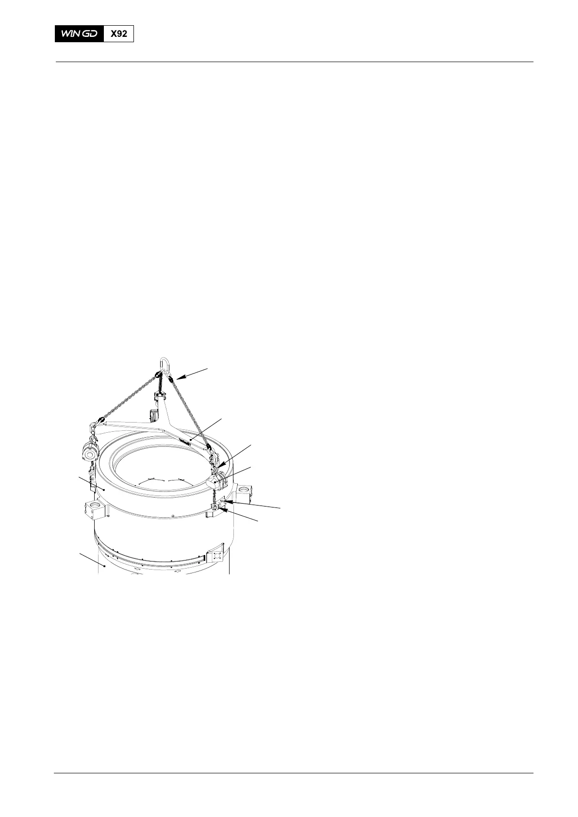
2. Bottom Water Guide
Jacket − Removal
1) Remove the cylinder liner holder and
pin (4, Fig. 2).
2) Attach the three eye bolts (94045-M10)
to the bottom water guide jacket (1,
Fig. 1).
3) Attach the three chain blocks
(94017−004) to the lifting tool (94205)
and the eye bolts (9405−M10).
4) Apply a light tension to the chain blocks (94017−004).
5) Remove the three bolts (3).
6) Attach the engine room crane to the chain (94205A).
7) Operate carefully the three chain blocks (94017−004) to lift the water guide
jacket (1).
8) Operate the engine room crane to lower the bottom water guide jacket on to an
applicable surface.
2017
Cylinder Liner
Fig. 1
94205
94016−003
2
1
94045−M10
3
94205A
WCH03843
94019H