8-38
SIGNALING SYSTEM
ELEC
YES NO
The wiring circuit
from the turn signal
switch to the turn sig-
nal light connector is
faulty and must be
repaired.
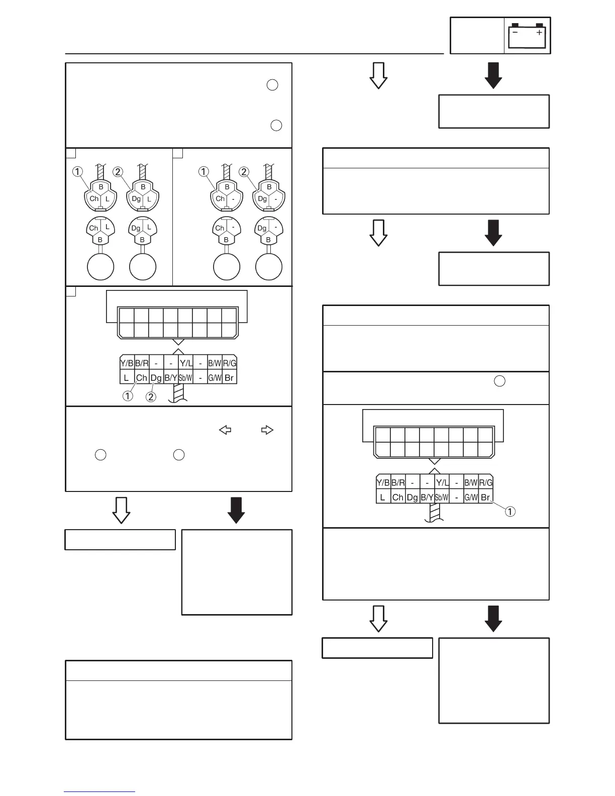
Left turn signal light
Positive tester probe ! chocolate
Negative tester probe ! ground
Right turn signal light
Positive tester probe ! dark green
Negative tester probe ! ground
1
2
S Turn the main switch to “ON”.
S Set the turn signal switch to “ ” or “ ”.
S Measure the voltage (DC 12 V) of the choco-
late or dark green at the turn signal light
connector (wire harness side).
S Is the voltage within specification?
1 2
This circuit is OK.
A B
C
1. Neutral indicator light (LEDs)
S Check the neutral indicator light for continu-
ity.
Refer to “CHECKING THE LEDs”
S Are the neutral indicator light OK?
EAS00801
4. The neutral indicator light fails to come on.
YES NO
Replace the meter
assembly.
YES NO
2. Neutral switch
S Check the neutral switch for continuity.
Refer to “CHECKING THE SWITCHES”.
S Is the neutral switch OK?
Replace the neutral
switch.
YES NO
3. Voltage
S Connect the pocket tester (DC 20 V) to the
meter assembly coupler (wire harness side)
as shown.
The wiring circuit
from the main switch
to the meter assem-
bly coupler is faulty
and must be re-
paired.
Positive tester probe ! brown
Negative tester probe ! ground
1
S Turn the main switch to “ON”.
S Measure the voltage (DC 12 V) of brown at
the meter assembly coupler (wire harness
side).
S Is the voltage within specification?
This circuit is OK.
 Loading...