8-40
SIGNALING SYSTEM
ELEC
YES NO
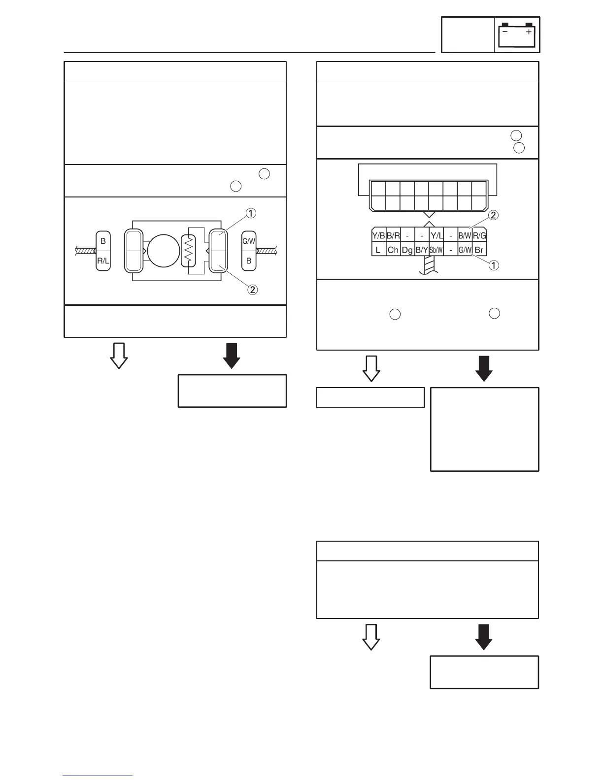
2. Fuel sender
S Drain the fuel from the fuel tank and remove
the fuel pump from the fuel tank.
S Disconnect the fuel sender coupler from the
wire harness.
S Connect the pocket tester (Ω 1) to the fuel
sender as shown.
Replace the fuel
pump assembly.
Positive tester probe ! green/white
Negative tester probe ! black
1
2
S Check the fuel sender for continuity.
S Is the fuel sender OK?
YES NO
3. Voltage
S Connect the pocket tester (DC 20 V) to the
meter assembly coupler (wire harness side)
as shown.
The wiring circuit
from the main switch
to the meter assem-
bly coupler is faulty
and must be re-
paired.
Positive tester probe ! green/white
Negative tester probe ! black/white
1
2
S Turn the main switch to “ON”.
S Measure the voltage (DC 12 V) of
green/white and black/white at the
meter assembly coupler.
S Is the voltage within specification?
This circuit is OK.
1
2
YES NO
1. Multi-function meter LEDs
S Check the multi-function meter LEDs for
continuity.
Refer to “CHECKING THE LEDs”.
S Is the multi-function meter LEDs OK?
Replace the meter
assembly.
EAS00806
7. The speedometer fails to operate.
 Loading...