6 Parameter Setting and Functions
6.5.2 Using the Holding Brake
6-40
This output signal controls the brake when using a servomotor with a brake and does not
have to be connected when using a servomotor without a brake.
Related Parameters
The output signal in the following parameter must be selected when the /BK signal is used.
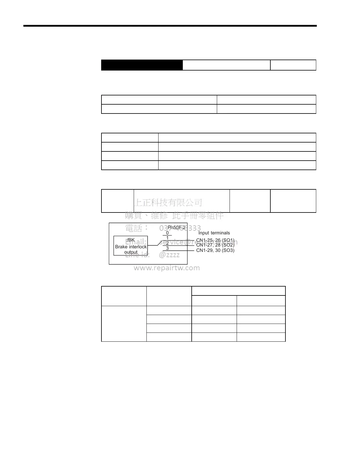
Select the /BK output terminal.
Note: Signals are output with OR logic when multiple signals are allocated
to the same output circuit. Set other output signals to a value other
than that allocated to the /BK signal in order to output the /BK signal
alone. Refer to 6.4.3 Output Circuit Signal Allocation.
Output → /BK
Brake Interlock Output Position Control
ON: Closed or low level Releases the brake.
OFF: Open or high level Applies the brake.
Pn505 Brake operation
Pn506 Time Delay from Brake Reference until Servo OFF
Pn507 Speed Level for Brake Reference Output during Motor Operation
Pn508 Timing for Brake Reference Output during Motor Operation
Pn50F Output Signal Selections 2 Factory
Setting:
0000
Position Control
Parameter Setting Output Terminal (CN1-)
∗
1
∗
2
Pn50F.2
0 −−
12526
22728
32930
/BK
Brake interlock
output
Input terminals
CN1-25, 26 (SO1)
CN1-27, 28 (SO2)
CN1-29, 30 (SO3)
1
2
3
0
Pn50F.2

 Loading...


