B.2 Function Switches
B-13
B
Position-
related
Switches
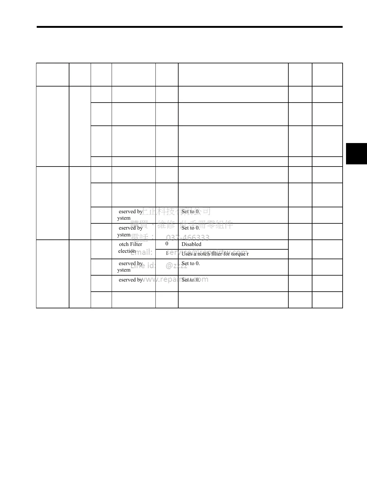
Pn200
0 Reference Pulse
Form
0 to 9
Set to 0.
0
∆
1 Error Counter
Clear Signal
Form
0 to 3
Set to 0.
0
∆
2 Clear Operation
1
Does not clear error counter. (Possible to clear
error counter only with CLR signal.)
(Automatically sets to 1 when the NS115 is
connected.)
1
∆
3 Filter Selection
0 to 1
Set to 0.
0
∆
Position-
related
Switches
Pn207
0 Reserved by
system
Set to 0.
0
∆
1 Position Control
Option
1
Uses V-REF as a speed feed-forward input.
(Automatically sets to 1 when the NS115 is
connected.)
1
∆
2 Reserved by
system
Set to 0.
0
3 Reserved by
system
Set to 0.
0
Torque-
related
Switches
Pn408 0 Notch Filter
Selection
0
Disabled
0
1
Uses a notch filter for torque reference.
1 Reserved by
system
Set to 0.
0
2 Reserved by
system
Set to 0.
0
3 Reserved by
system
Set to 0.
0
Table B.3 Function Switches List (cont’d)
Category Pn No. Digit
Place
Name Setting Description SGDH
Factory
Setting
Changing
Method *

 Loading...


