6.1 I/O Signal Allocations
6.1.5 /WARN (Warning) Signal
6-11
6.1.5
/WARN (Warning) Signal
Both alarms and warnings are generated by the SERVOPACK. Alarms indicate errors in the
SERVOPACK for which operation must be stopped immediately. Warnings indicate situations
that may results in alarms but for which stopping operation is not yet necessary.
The /WARN (Warning) signal indicates that a condition exists that may result in an alarm.
Note: You must allocate the /WARN signal to use it. Use Pn50F = n.X (/WARN (Warning Output) Signal Allo-
cation) to allocate the signal to a connector pin. Refer to the following section for details.
6.1.2 Output Signal Allocations on page 6-8
Setting the Warning Code Output
You can use the ALO1 to ALO3 (Alarm Code Output) signals to output warning codes. Use
Pn001 = n.X (Warning Code Output Selection) to set the output.
Refer to the following sections for details on the warnings.
12.3.1 List of Warnings on page 12-48
6.1.6
/TGON (Rotation Detection) Signal
The /TGON signal indicates that the Servomotor is operating.
This signal is output when the shaft of the Servomotor rotates at the setting of Pn502 (Rotation
Detection Level) or faster or the setting of Pn581 (Zero Speed Level) or faster.
The /TGON signal is allocated to CN1-27 and CN1-28 by default.
Note: Use Pn50E = n.X (/TGON (Rotation Detection Output) Signal Allocation) to allocate the /TGON signal to
another connector pin. Refer to the following section for details.
6.1.2 Output Signal Allocations on page 6-8
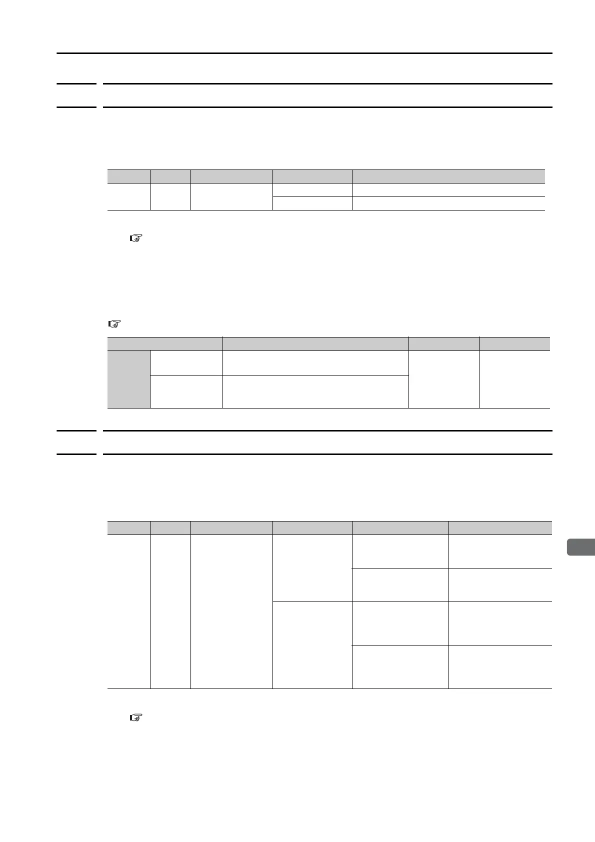
Typ e Signal Connector Pin No. Signal Status Meaning
Output /WARN Must be allocated.
ON (closed) Warning
OFF (open) Normal status
Parameter Description When Enabled Classification
Pn001
n.0
(default setting)
Output only alarm codes on the ALO1 to
ALO3 terminals.
After restart Setup
n.1
Output both warning codes and alarm codes
on the ALO1 to ALO3 terminals. If there is an
alarm, the alarm code is output.
Typ e Signal Connector Pin No. Signal Status Servomotor Meaning
Output /TGON
CN1-27 and CN1-
28 (default setting)
ON (closed)
Rotary Servomotors
The Servomotor is
operating at the setting
of Pn502 or faster.
Linear Servomotors
The Servomotor is
operating at the setting
of Pn581 or faster.
OFF (open)
Rotary Servomotors
The Servomotor operat-
ing at a speed that is
slower than the setting
of Pn502.
Linear Servomotors
The Servomotor is
operating at a speed
that is slower than the
setting of Pn581.

 Loading...


