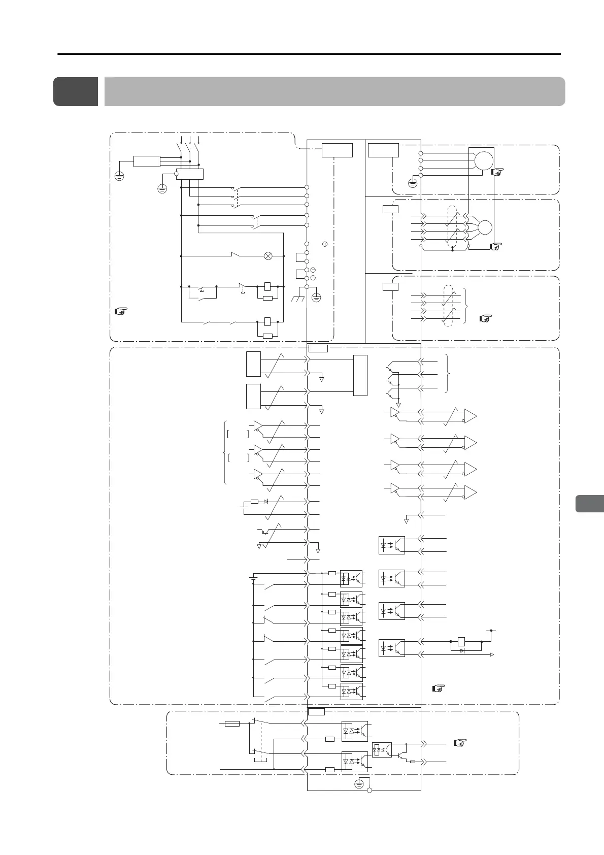
Battery for absolute
encoder
*2
2.8 V to 4.5 V
Connect shield to connector shell.
Connector shell
Speed reference input
Ground to
a resistance
of 100 Ω
or less.
Torque reference input
Maximum input voltage: ±12 V
Alarm Code Output
(OFF for alarm)
Switch
Fuse
0 V
Safety
*3
Maximum input voltage: ±12 V
Encoder Divided
Pulse Output,
Phase A
Encoder Divided
Pulse Output,
Phase B
Encoder Divided
Pulse Output,
Phase C
Position Reference
Phase A
Phase B
*5
Absolute encoder
position output
*2
BAT(+)
BAT(-)
PBO
PCO
/PBO
PAO
/PAO
/PCO
/SO1+
(/V-CMP+, /COIN+)
/SO1-
(/V-CMP-, /COIN-)
/SO2+
(/TGON+)
/SO2-
(/TGON-)
/SO3+
(/S-RDY+)
ALM+
ALM-
EDM1+
EDM1-
FG
22
21
10
27
28
29
30
31
32
25
26
19
33
34
35
36
20
+24 V
+24VIN
/SI0 (/S-ON)
/SI3 (/P-CON)
/SI1 (P-OT)
/SI2 (N-OT)
/SI4
(/ALM-RST)
/SI6 (/N-CL)
47
41
43
42
44
45
/SI5 (/P-CL)
46
40
/SO3-
(/S-RDY-)
General-purpose sequence input 0
(Servo ON input: ON to turn ON servo)
Sequence input signal
power supply input
Overheat protection input
General-purpose sequence input 2
(Reverse Drive Prohibit input: OFF to prohibit drive)
General-purpose sequence input 1
(Forward Drive Prohibit input: OFF to prohibit drive)
General-purpose sequence input 4
(Alarm Reset input: ON to reset alarm)
General-purpose sequence input 6
(Reverse External Torque Limit input: ON to limit)
General-purpose sequence input 5
(Forward External Torque Limit input: ON to limit)
Frame ground
General-purpose sequence input 3
(Proportional Control input: ON for proportional action)
General-purpose sequence output 2
(Rotation Detection output:
ON at setting or higher)
Servo Alarm output
General-purpose sequence output 3
(Servo Ready output: ON when /
S-ON signal can be received)
General-purpose sequence output 1
(Speed Coincidence Detection output:
ON for coincidence, Positioning Completion
output: ON for completion)
Signal ground
V-REF
SG
A/D
5
6
*1
T-REF
SG
1
SG
9
2
+5 V
0 V
SEN
SG
4
Absolute data
request input
*4
TH
50
ALO1
ALO2
ALO3
37
38
39
/HWBB1+
/HWBB1-
/HWBB2+
/HWBB2-
24 V
6
3
4
5
8
7
D/A
D/A
PSO
/PSO
48
49
*6
*1
*6
*6
*6
PULS
SIGN
CLR
CW
CCW
/PULS
SIGN
/SIGN
PULS
14
15
CLR
/CLR
12
11
8
7
*1
*1
CN1
CN8
1
2
5
6
ENC
PS
/PS
PG5V
PG0V
2
4
1
3
0 V
1Ry
1D
+24 V
CN5
L1
U
V
W
M
B2
B3
L2
L1C
L3
L2C
1
2
B1/
2KM
1KM
1QF
R
S T
1FLT
3SA
1PL
1KM
2KM
1SA
2SA
1KM
1Ry
1KM
1Ry
CN2
Main circuit
terminals
Analog Monitors
SERVOPACK
(For servo alarm
display)
Servo power
ON
Servo power
OFF
Motor
terminals
+
-

 Loading...


