6.17 Forcing the Motor to Stop
6.17.1 FSTP (Forced Stop Input) Signal
6-106
6.17
Forcing the Motor to Stop
You can force the Servomotor to stop for a signal from the host controller or an external device.
To force the motor to stop, you must allocate the FSTP (Forced Stop Input) signal in Pn516 =
n.X. You can specify one of the following stopping methods: dynamic brake (DB), coast-
ing to a stop, or decelerating to a stop.
Note: Forcing the motor to stop is not designed to comply with any safety standard. In this respect, it is different
from the hard wire base block (HWBB).
6.17.1
FSTP (Forced Stop Input) Signal
Note: You must allocate the FSTP signal to use it. Use Pn516 = n.X (FSTP (Forced Stop Input) Signal Alloca-
tion) to allocate the FSTP signal to a connector pin. Refer to the following section for details.
6.1.1 Input Signal Allocations on page 6-5
6.17.2
Stopping Method Selection for Forced Stops
Use Pn00A = n.X (Stopping Method for Forced Stops) to set the stopping method for
forced stops.
Note: You cannot decelerate a Servomotor to a stop during torque control. For torque control, the Servomotor will
be stopped with the dynamic braking or coast to a stop according to the setting of Pn001 = n.X (Motor
Stopping Method for Servo OFF and Group 1 Alarms).
Panel Display and Digital Operator Display
When a forced stop is performed, the panel display will display FST and the Digital Operator
will display FSTP.
To prevent accidents that may result from contact faults or disconnections, use a normally
closed switch for the Forced Stop Input signal.
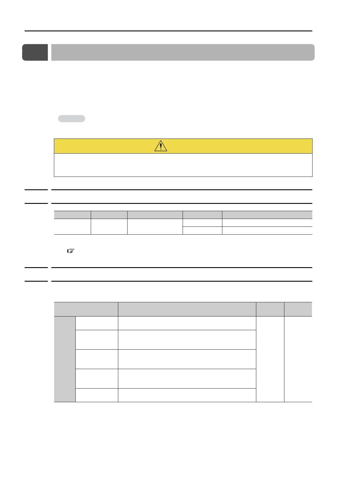
Classification Signal Connector Pin No. Signal Status Description
Input FSTP Must be allocated.
ON (closed) Drive is enabled (normal operation).
OFF (open) The motor is stopped.
Parameter Description
When
Enabled
Classifi-
cation
Pn00A
n.0
Apply the dynamic brake or coast the motor to a stop
(use the stopping method set in Pn001 = n.X).
After
restart
Setup
n.1
(default setting)
Decelerate the motor to a stop using the torque set in
Pn406 as the maximum torque. Use the setting of Pn001
= n.X for the status after stopping.
n.2
Decelerate the motor to a stop using the torque set in
Pn406 as the maximum torque and then let the motor
coast.
n.3
Decelerate the motor to a stop using the deceleration
time set in Pn30A. Use the setting of Pn001 = n.X
for the status after stopping.
n.4
Decelerate the motor to a stop using the deceleration
time set in Pn30A and then let the motor coast.

 Loading...


