1.3 Part Names
1-4
1.3
Part Names
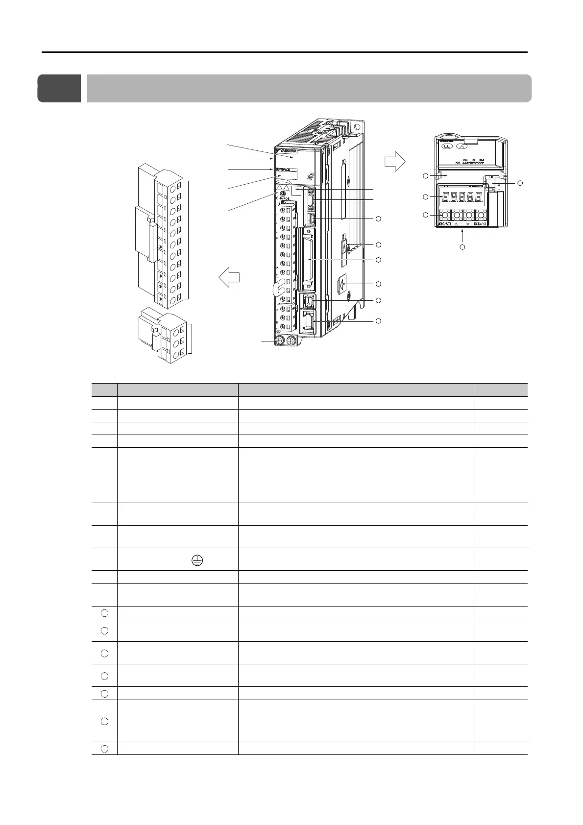
No. Name Description Reference
Front Cover −−
Nameplate Indicates the SERVOPACK model and ratings. page 1-3
Input Voltage − –
Model The model of the SERVOPACK. page 1-6
CHARGE
Lit while the main circuit power is being supplied.
Note: Even if you turn OFF the main circuit power supply, this
indicator will be lit as long as the internal capacitor remains
charged. Do not touch the main circuit or motor terminals
while this indicator is lit. Doing so may result in electric
shock.
−
Main Circuit Terminals
The terminals depend on the main circuit power supply
input specifications of the SERVOPACK.
page 4-11
Servomotor Terminals (U, V,
and W)
The connection terminals for the Servomotor Main Circuit
Cable (power line).
page 4-25
Ground Terminal ( )
The ground terminals to prevent electric shock. Always
connect this terminal.
−
QR Code The QR code that is used by the MechatroCloud service. −
Serial Communications Con-
nector (CN3)
Connects to the Digital Operator (a peripheral device) or a
computer (RS-422).
page 4-50
Computer Connector (CN7) A USB connector to connect a computer. page 4-50
Safety Option Module Con-
nector
Connects to a Safety Option Module. −
I/O Signal Connector (CN1)
Connects to reference input signals and sequence I/O sig-
nals.
page 4-33
Feedback Option Module
Connector
Connects to a Feedback Option Module. −
Safety Connector (CN8) Connects to a safety function device. page 4-48
Encoder Connector (CN2)
• Rotary Servomotor: Connects to the encoder in the Ser-
vomotor.
• Linear Servomotor: Connects to a Serial Converter Unit
or linear encoder.
page 4-25
Serial Number −−
Continued on next page.
(on side of
SERVOPACK)
Main circuit
terminals
Motor
terminals
With Front Cover Open
L2L1 L3
L1C
L2C
B1/
B2 B3
12
U V W
11
12
13
14
18
19
20
15
21
16
17

 Loading...


