13.3 Monitor Display (Un) Operations on the Panel Operator
13.3.5 Upper Limit Setting Monitor for Maximum Motor Speed/Upper Limit Setting for Encoder Output Resolution (Un010)
13-11
Panel Displays and Panel Operator Procedures
Display Example
A display example for safety input signals is shown below.
• When the /HWBB1 Signal Turns OFF to Activate a HWBB
13.3.5
Upper Limit Setting Monitor for Maximum Motor Speed/
Upper Limit Setting for Encoder Output Resolution
(Un010)
You can use Un010 to monitor the upper limit setting for the maximum motor speed or the
upper limit setting for the encoder output resolution.
You can monitor the upper limit of the encoder output resolution setting (Pn281) for the current
maximum motor speed setting (Pn385), or you can monitor the upper limit of the maximum
motor speed setting for the current encoder output resolution setting.
Select which signal to monitor with Pn080 = n.X (Calculation Method for Maximum
Speed or Encoder Output Pulses).
• If Pn080 = n.0, the encoder output resolution (Pn281) that can be set is displayed.
• If Pn080 = n.1, the maximum motor speed (Pn385) that can be set is displayed in mm/
s.
13.3.6
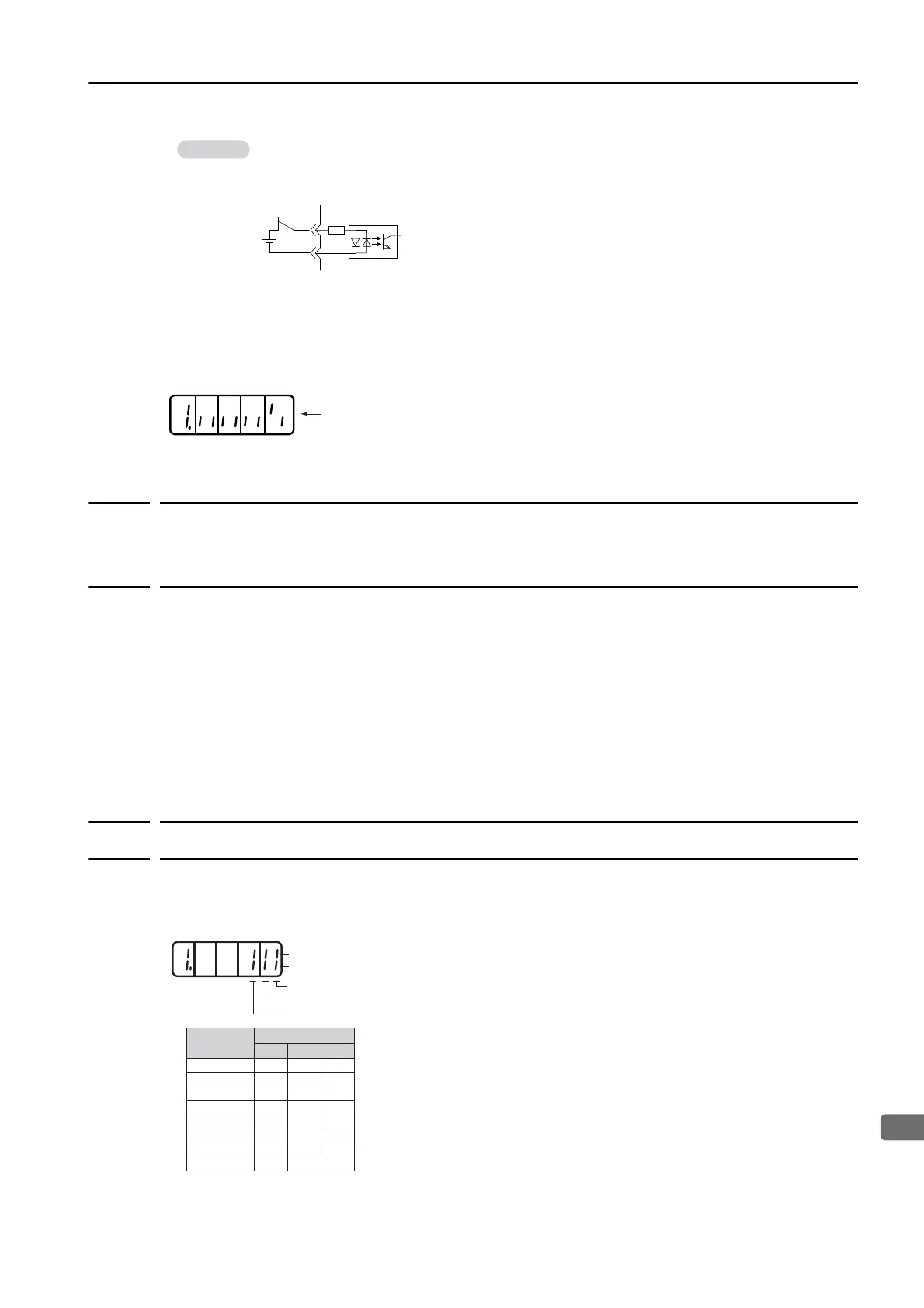
Polarity Sensor Signal Monitor (Un011)
You can use Un011 to monitor the signal pattern of the polarity sensor.
Press the DATA/SHIFT Key for approximately one second to display the polarity sensor signal
pattern.
The configuration of the input circuits is shown below.
OFF: Open
ON: Closed
Example:
76543 218
The bottom segment of digit 1 is lit.
L
L
L
L
H
H
H
H
0
1
2
3
4
5
6
7
L
L
H
H
L
L
H
H
L
H
L
H
L
H
L
H
Bottom segment: OFF (low level)
Phase-W signal monitor
Phase-V signal monitor
Phase-U signal monitor
Polarity Sensor
Signal Pattern
Signal Monitor
Phase W
Phase VPhase U
Top segment: ON (high level)

 Loading...


