6.12 Absolute Encoders
6.12.1 Connecting an Absolute Encoder
6-74
6.12.1
Connecting an Absolute Encoder
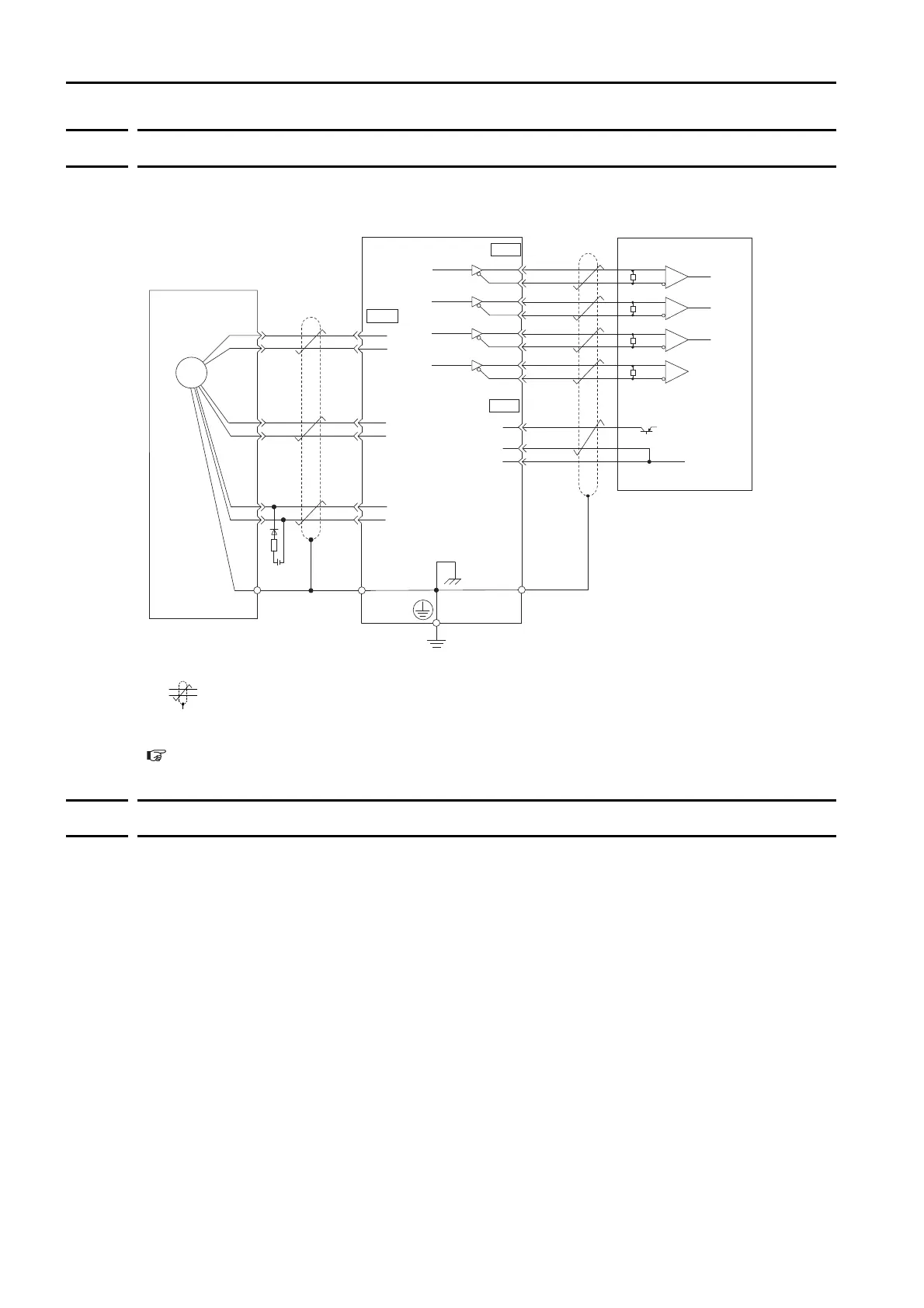
The following diagram shows the typical connections between a Servomotor with an absolute encoder,
the SERVOPACK, and the host controller.
*1.
The absolute encoder pin numbers for wiring the connector depend on the Servomotor that you use.
*2.
represents a shielded twisted-pair cable.
*3.
If you use an Encoder Cable with a Battery Case, do not install a battery at the host controller.
Refer to the following section for details on the typical connections.
4.4.3
Wiring the SERVOPACK to the Encoder
on page 4-26
6.12.2
Structure of the Position Data of the Absolute Encoder
The position data of the absolute encoder is the position coordinate from the origin of the absolute
encoder.
The position data from the absolute encoder contains the following two items.
•
The number of rotations from the origin of the encoder coordinate system (called the multiturn data)
•
The position (number of pulses) within one rotation
The position data of the absolute encoder is as follows:
Position data of absolute encoder = Multiturn data
×
Number of pulses within one encoder rotation
(setting of Pn212)+ Position (number of pulses) within one rotation.
For a single-turn absolute encoder, the multiturn data is 0.
+-
/PCO
3
4
4
2
SG
SEN
CN2
33
34
35
36
19
20
CN1
SG
1
PAO
/PAO
PBO
/PBO
PCO
Absolute encoder
(Shell)
Battery
SERVOPACK
Output line driver:
SN75ALS174
or the equivalent
Encoder Cable
with a Battery Case
Connector
shell
Connector
shell
CN1
*2
*2
*1
0 V
+5 V
Host controller
Applicable Line Receiver: SN75ALS175 or
MC3486 manufactured
by Texas Instruments
or the equivalent
5
6
1
2
PG5 V
PG0 V
PS
/PS
BAT(+)
BAT(-)
Phase A
Phase B
Phase C
R
R
R
*3
/PSO
PSO
R
R (terminating resistance): 220 Ω to 470 Ω
Phase A
Phase B
Phase C
ENC

 Loading...


