4.4 Wiring Servomotors
4.4.4 Wiring the SERVOPACK to the Holding Brake
4-32
4.4.4
Wiring the SERVOPACK to the Holding Brake
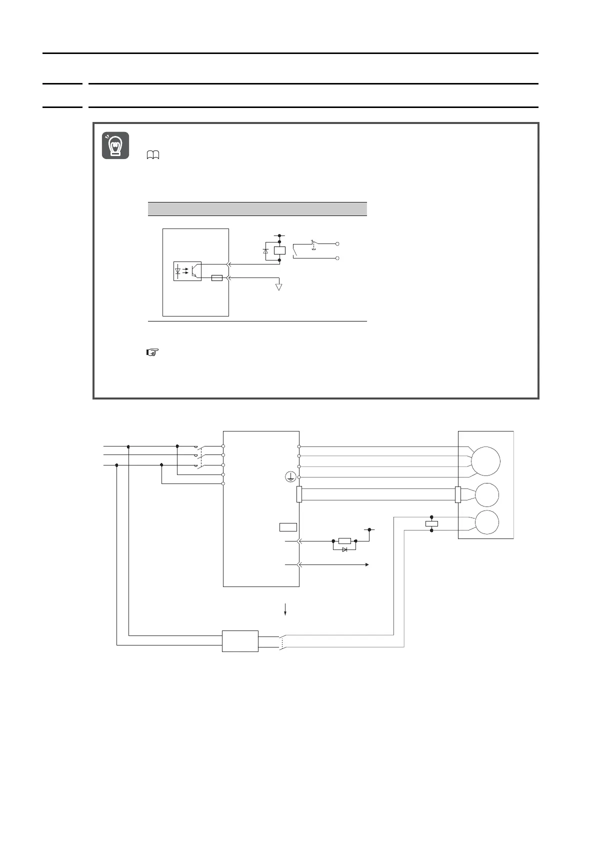
* Install the surge absorber near the brake terminals on the Servomotor.
• If you use a Rotary Servomotor, select a Surge Absorber according to the brake current and
brake power supply. Refer to the following manual for details.
Σ-7-Series Peripheral Device Selection Manual (Manual No.: SIEP S800001 32)
• After the Surge Absorber is connected, check the brake operation delay time in your applica-
tion. The Surge Absorber may affect the brake operation delay time.
Configure the relay circuit to activate the holding brake for an emergency stop.
• The /BK (Brake) signal cannot be used with the default settings. You must allocate the output
signal. Refer to the following section for details.
Allocating the /BK (Brake) Signal
on page 5-38
• If you use a 24-V brake, install a separate power supply for the 24-VDC power supply from
other power supplies, such as the one for the I/O signals of the CN1 connector. If the power
supply is shared, the I/O signals may malfunction.
0V
Emergency stop
5 VDC to 30 VDC
SERVOPACK
Photocoupler
Servomotor with
Holding Brake
SERVOPACK
Surge Absorber
Power supply
BK-RY: Brake control relay
1D: Flywheel diode
M
BK
ENC
U
V
W
CN2
AC DC
BK-RY
BK-RY
+24 V
L1
L2
L3
L1C
L2C
(/BK+)
(/BK-)
CN1
Brake power supply
DC side
1D
0 V
*

 Loading...


