9.3 Monitoring Machine Operation Status and Signal Waveforms
9.3.3 Using a Measuring Instrument
9-11
* Refer to the following section for details.
8.12.1 Gain Switching on page 8-66
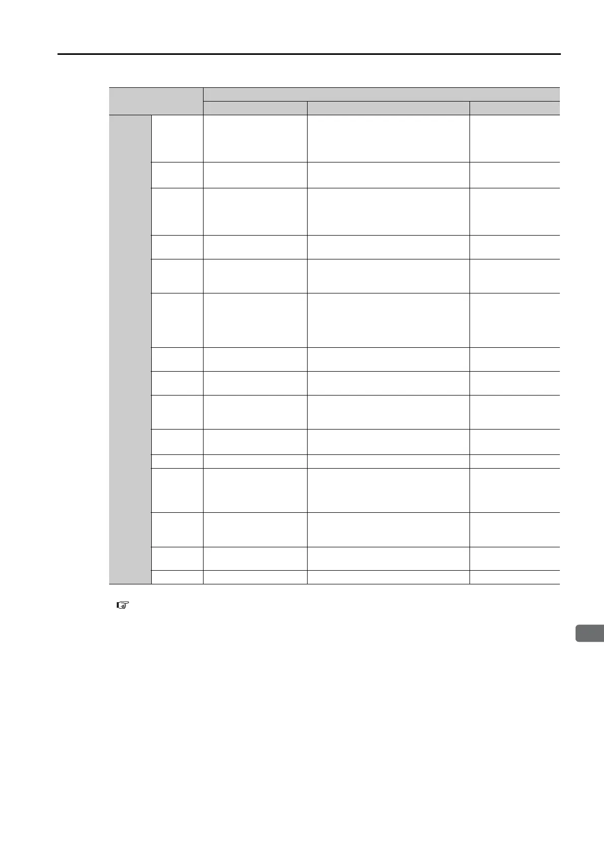
Parameter
Description
Monitor Signal Output Unit Remarks
Pn006
or
Pn007
n.00
(default
setting of
Pn007)
Motor Speed
• Rotary Servomotor: 1 V/1,000 min
-1
• Linear Servomotor: 1 V/1,000 mm/s
–
n.
01 Speed Reference
• Rotary Servomotor:1 V/1,000 min
-1
• Linear Servomotor:1 V/1,000 mm/s
–
n.02
(default
setting of
Pn006)
Torque Reference 1 V/100% rated torque –
n.
03 Position Deviation 0.05 V/Reference unit
0 V for speed or
torque control
n.
04
Position Amplifier Devi-
ation
0.05 V/encoder pulse unit
Position deviation
after electronic gear
conversion
n.
05
Position Command
Speed
• Rotary Servomotor:1 V/1,000 min
-1
• Linear Servomotor:1 V/1,000 mm/s
The input reference
pulses will be multi-
plied by n to output
the position com-
mand speed.
n.
06
Reserved parameter
(Do not change.)
––
n.
07
Motor - Load Position
Deviation
0.01 V/Reference unit –
n.
08 Positioning Completion
Positioning completed: 5 V
Positioning not completed: 0 V
Completion is indi-
cated by the output
voltage.
n.
09 Speed Feedforward
• Rotary Servomotor:1 V/1,000 min
-1
• Linear Servomotor:1 V/1,000 mm/s
–
n.0A Torque Feedforward 1 V/100% rated torque –
n.
0B
Active Gain
*
1st gain: 1 V
2nd gain: 2 V
The gain that is
active is indicated
by the output volt-
age.
n.0C
Completion of Position
Reference Distribution
Distribution completed: 5 V
Distribution not completed: 0 V
Completion is indi-
cated by the output
voltage.
n.
0D
External Encoder
Speed
1 V/1,000 min
-1
Value calculated at
the motor shaft
n.
10 Main Circuit DC Voltage 1 V/100 V (main circuit DC voltage) –

 Loading...


