4.7 DeviceNet System Configuration
4.7.4 Signal Names and Functions of the DeviceNet Communications Connector (CN6)
4-45
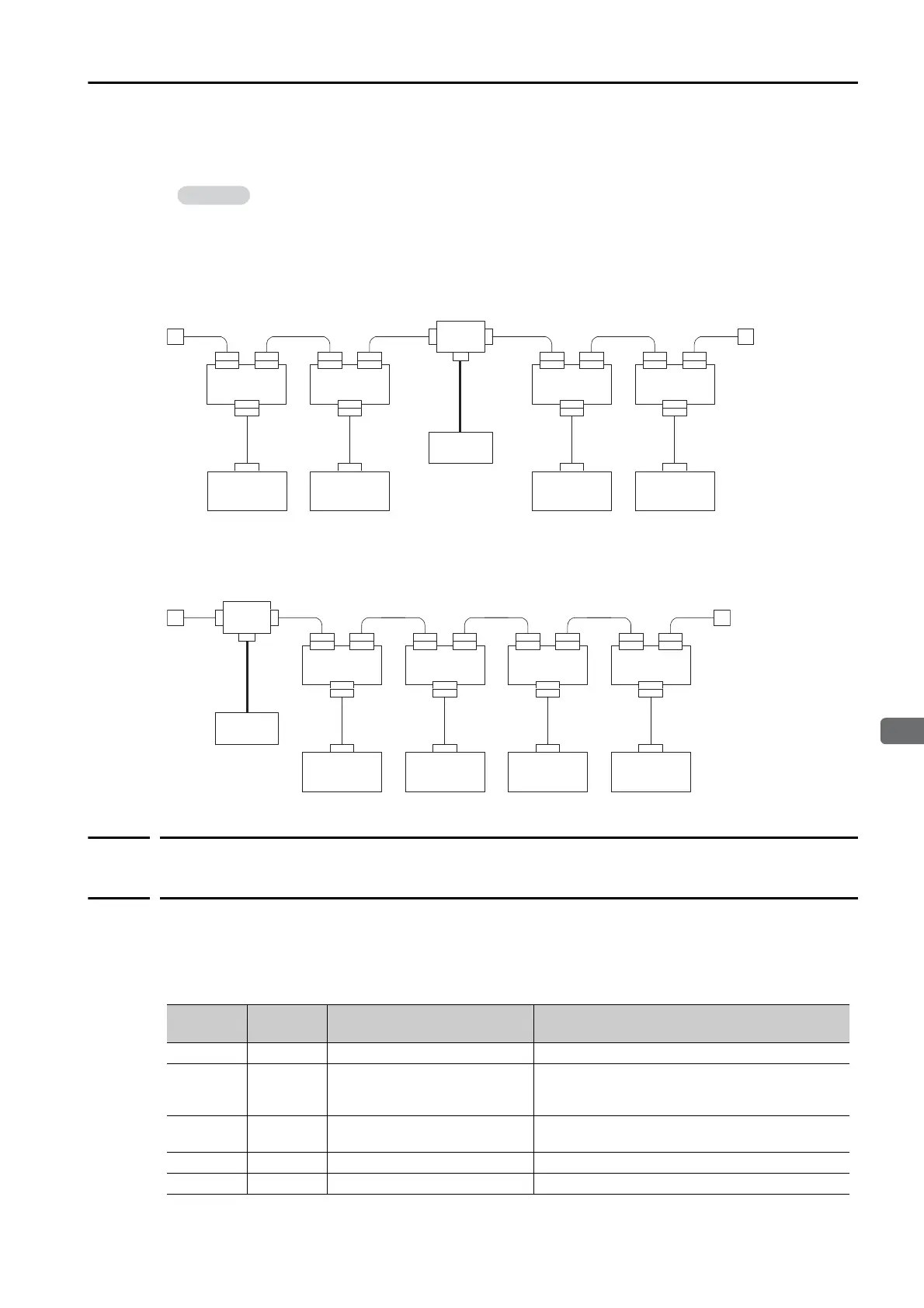
Location of Power Supply
The following two types of configuration are possible for the location of the power supply.
Nodes on Both Sides of the Power Supply
Nodes on One Side of the Power Supply
4.7.4
Signal Names and Functions of the DeviceNet
Communications Connector (CN6)
This section gives the signal names, functions, pin arrangement, and connector specifications
of the DeviceNet communications connector (CN6).
I/O Signals
We recommend that you place nodes on both sides of the power supply if a single power
supply is connected to many nodes.
Communications
Power Supply
Power supply tap
or T-branch adapter
Node Node Node Node
T-branch
adapter
T-branch
adapter
T-branch
adapter
T-branch
adapter
Communications
power supply
Power supply tap
or T-branch adapter
Node Node Node Node
T-branch
adapter
T-branch
adapter
T-branch
adapter
T-branch
adapter
Signal
Name
Pin No. Name Function
SHIELD 1 Cable shield –
24 V 2
Communications power sup-
ply +24 V
This pin is used to input the control power supply
for DeviceNet communications.
Operating range: +11 V to +25 V
0 V 3
Communications power sup-
ply 0 V
–
CAN H 4 CAN bus line dominant H –
CAN L 5 CAN bus line dominant L –
 Loading...


