4.7 DeviceNet System Configuration
4.7.5 Network Connection Methods
4-46
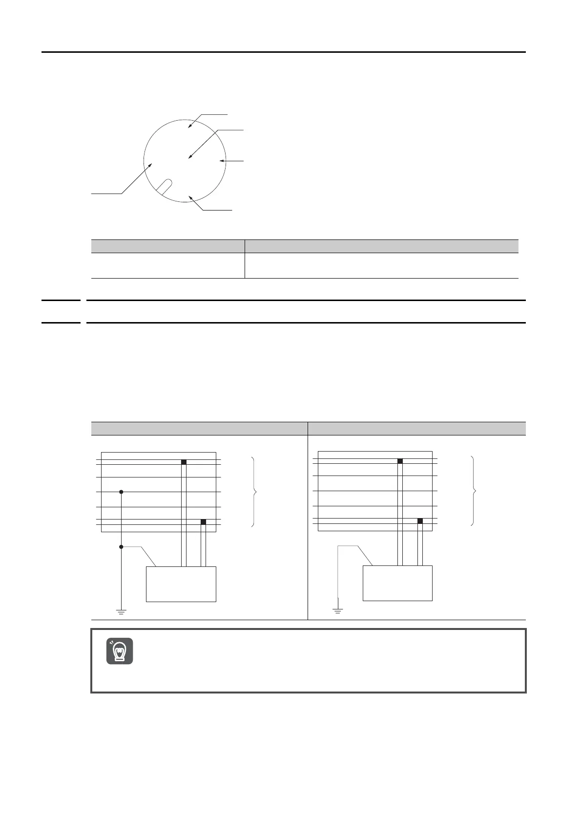
Pin Arrangement and Connector
4.7.5
Network Connection Methods
Connect the shield wire of the cable to the FG terminal of the communications power supply
and ground the shield wire.
If more than one power supply is used for communications, ground only the power supply that
is located closest to the middle of the network through the shield wire. Do not ground the
power supply through the shield wire at any other point.
If more than one power supply is connected to the network, connect each of them using a
power supply tap.
Name Model
Micro-style Connector (FEMALE) OMRON DCA1-5CN02F1 Cable with Connectors or the equivalent.
SHIELD
CAN H
CAN L
0 V
24 V
Power Supply with Single-Point Ground Power Supply without Ground
• Power supplies are not counted as nodes.
• Ground the network to a resistance of 100 Ω or less.
• Do not ground the network together with servo drives or AC drives.
• Do not ground the network through the shield wire at more than one point. Ground it at a
single point only.
Communications
power supply
V+
CAN H
Shield
CAN L
V-
T-branch adapter or power supply tap
Communications
cable
V+ V-FG
Ground
Communications
power supply
V+
CAN H
Shield
CAN L
V-
Power supply tap
Communications
cable
V+ V-FG
Ground
Important
 Loading...


