8.11 Speed Ripple Compensation
8.11.3 Setting Parameters
8-64
10.
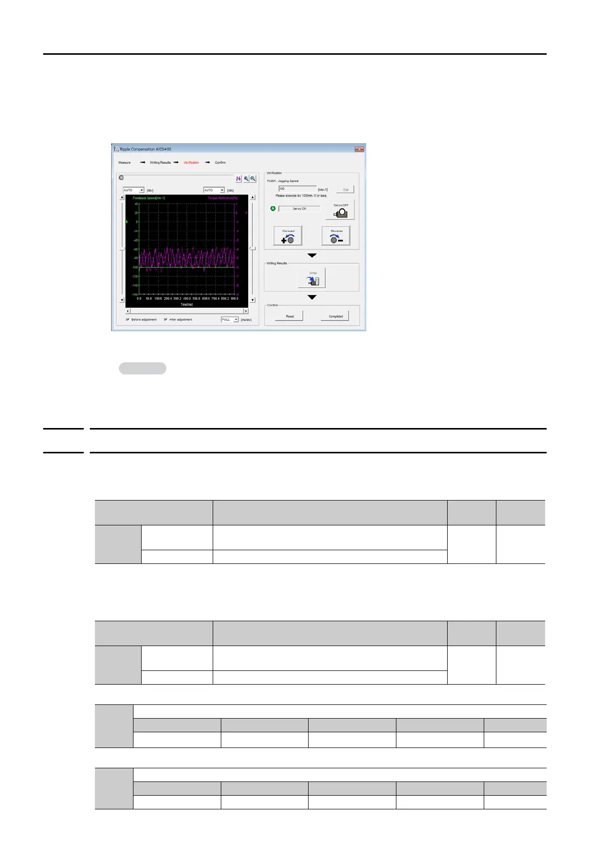
Click the Forward Button or the Reverse Button.
Verification operation is started.
The Servomotor shaft will rotate at the preset jogging speed while you hold down the Forward or
Reverse Button.
The waveform with speed ripple compensation applied to it will be displayed.
11.
If the verification results are OK, click the Completed Button.
This concludes the setup for speed ripple compensation.
8.11.3
Setting Parameters
The function is enabled when you perform the operating procedure on Operating Procedure on
page 8-61. To cancel speed ripple compensation, use Pn423 = n.0 (Disable speed ripple
compensation) to disable it.
If you enable speed ripple compensation, a compensation reference will be applied to reduce
ripple even when stopped at a 0 speed reference. In speed control mode, this may result in the
Servomotor moving slightly. To prevent this, set Pn423 = n.X (Speed Ripple Compensa-
tion Selections) and Pn427 or Pn49F (Speed Ripple Compensation Enable Speed).
• For Rotary Servomotors
• For Linear Servomotors
To discard the setup results, click the Reset Button.
Parameter Description
When
Enabled
Classifi-
cation
Pn423
n.0
(default setting)
Disable speed ripple compensation.
After
restart
Setup
n.
1 Enable speed ripple compensation.
Parameter Description
When
Enabled
Classifi-
cation
Pn423
n.
0
(default setting)
Speed reference
After
restart
Setup
n.1 Motor Speed
Pn427
Speed Ripple Compensation Enable Speed
Setting Range Setting Unit Default Setting When Enabled Classification
0 to 10,000
1 min
-1
0 Immediately Tuning
Pn49F
Speed Ripple Compensation Enable Speed
Setting Range Setting Unit Default Setting When Enabled Classification
0 to 10,000 1 mm/s 0 Immediately Tuning
 Loading...


