3.4 Mounting Hole Dimensions
3-5
3.4
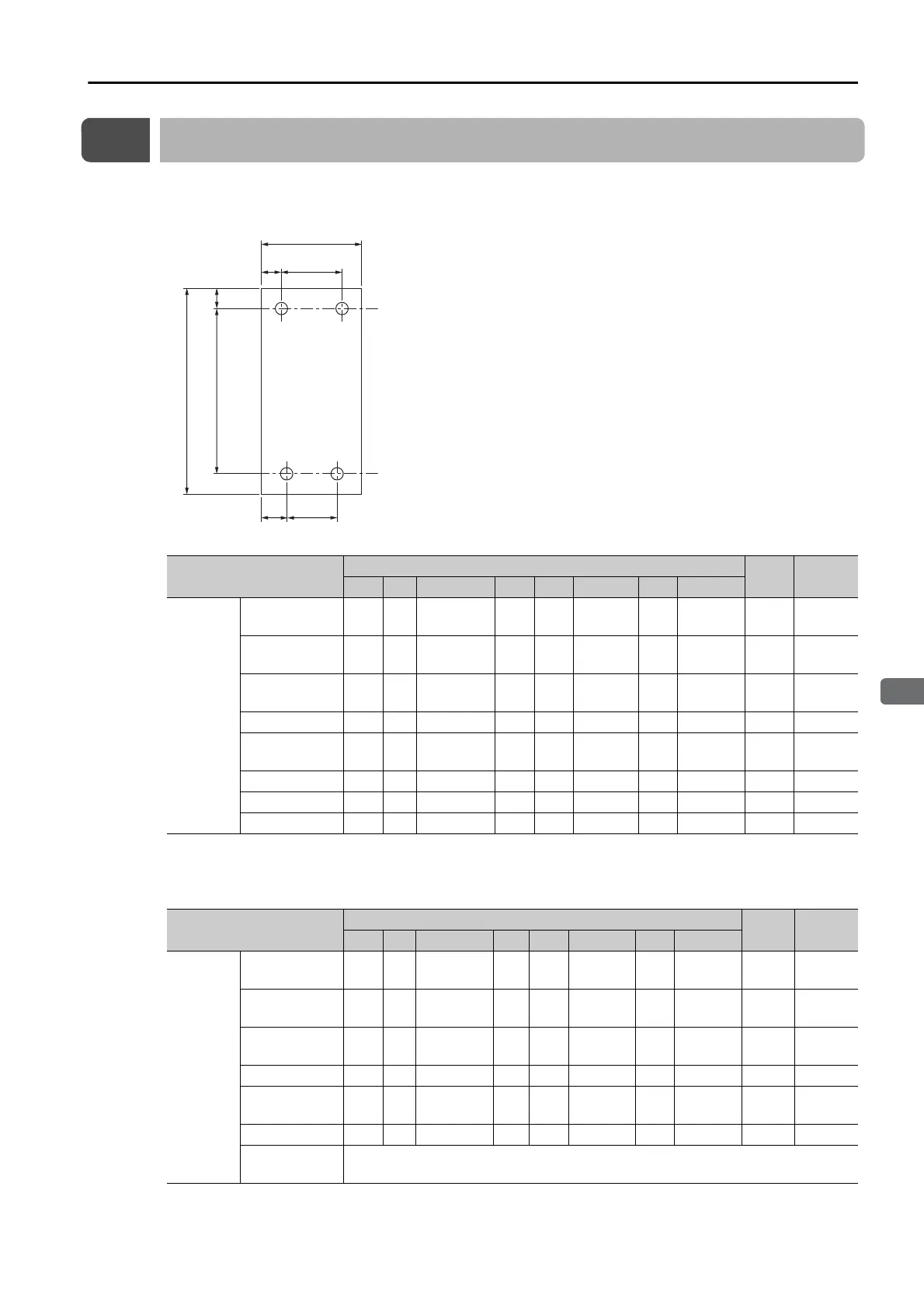
Mounting Hole Dimensions
Use mounting holes to securely mount the SERVOPACK to the mounting surface.
Note: To mount the SERVOPACK, you will need to prepare a screwdriver that is longer than the depth of the SERVOPACK.
Σ-7-series Mounting Hole Dimensions
Σ
-V-series-Compatible Mounting Hole Dimensions
If you are replacing a
Σ
-V-Series SERVOPACK with a
Σ
-7-Series SERVOPACK, you can also use the
mounting holes that were used for the
Σ
-V-Series SERVOPACK. Refer to the following table.
SERVOPACK Model
Dimensions (mm)
Screw
Size
Number
of Screws
A B C D E F G H
SGD7S-
R70A, R90A,
1R6A
168 5 160 ±0.5 40 35 − 25 − M4 2
2R8A, R70F,
R90F, 2R1F
168 5 160 ±0.5 40 5 − 25 − M4 2
3R8A, 5R5A,
7R6A, 2R8F
168 5 160 ±0.5 70 6 58 ±0.5 64 − M4 3
120A 168 5 160 ±0.5 90 5 80 ±0.5 12.5 − M4 3
180A, 200A,
120AE0A008
188 5 180 ±0.5 100 95 − 12.5 75 ±0.5 M4 3
330A 258 6 250 ±0.5 110 5 100 ±0.5 13 84 ±0.5 M5 4
470A, 550A 315 6 302.5 ±0.5 170 14 142 ±0.5 14 142 ±0.5 M6 4
590A, 780A 390 7.5 375 ±0.5 260 30 200 ±0.5 30 200 ±0.5 M6 4
SERVOPACK Model
Dimensions (mm)
Screw
Size
Number
of Screws
A B C D E F G H
SGD7S-
R70A, R90A,
1R6A
168 5 150 ±0.5 40 35 − 35 − M4 2
2R8A, R70F,
R90F, 2R1F
168 5 150 ±0.5 40 5 − 35 − M4 2
3R8A, 5R5A,
7R6A, 2R8F
168 5 150 ±0.5 70 6 58 ±0.5 6 − M4 3
120A 168 5 150 ±0.5 90 5 80 ±0.5 5 − M4 3
180A, 200A,
120AE0A008
188 5 170 ±0.5 100 95 − 590 ±0.5 M4 3
330A 250 6 238.5 ±0.5 110 5 100 ±0.5 5 100 ±0.5 M5 4
470A, 550A,
590A, 780A
A special attachment is required. Contact your Yaskawa representative for
details.
D
EF
H
A
BC
G
 Loading...


