4.5 I/O Signal Connections
4.5.2 I/O Signal Connector (CN1) Pin Arrangement
4-34
4.5.2
I/O Signal Connector (CN1) Pin Arrangement
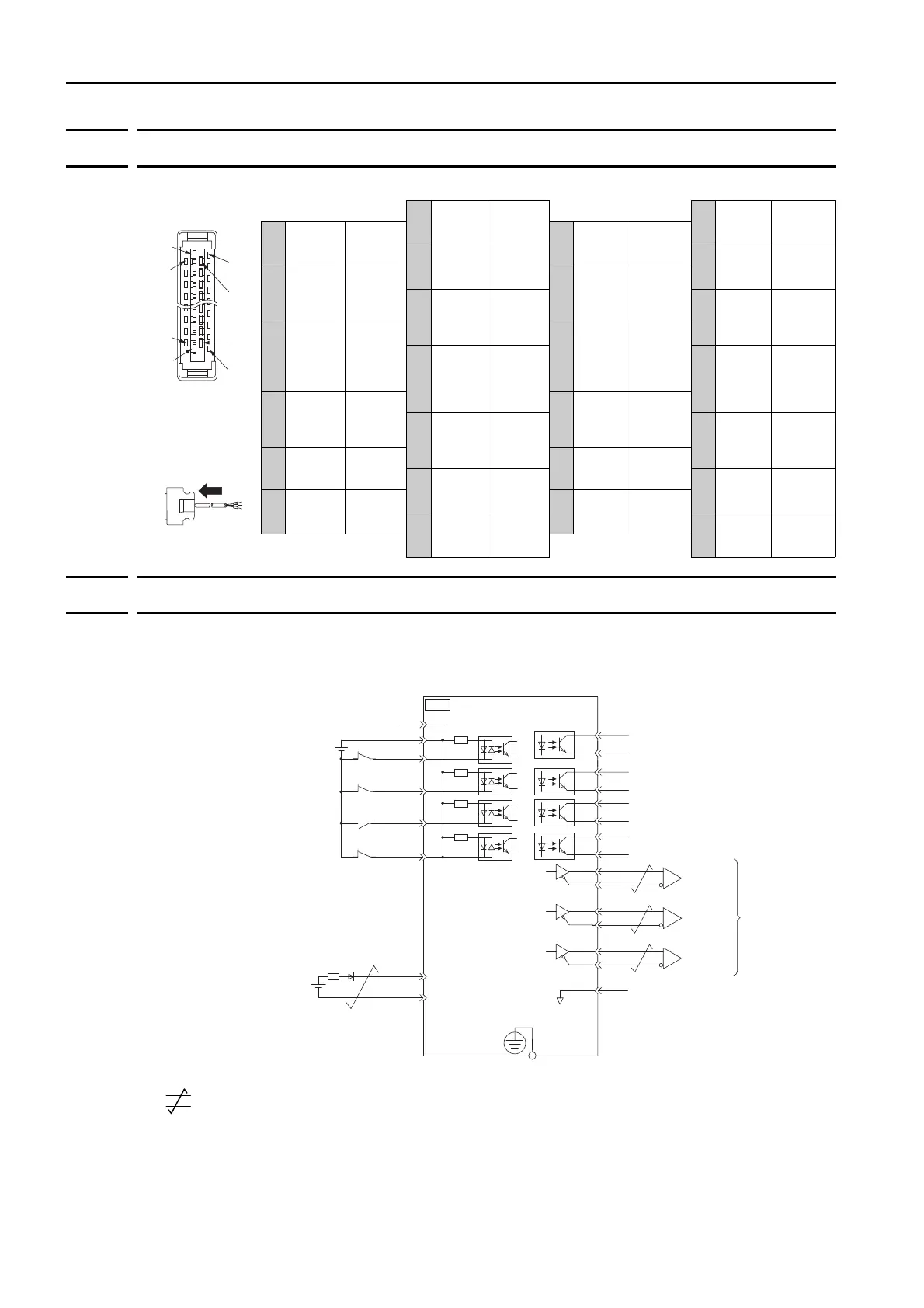
The following figure gives the pin arrangement of the I/O signal connector (CN1).
4.5.3
I/O Signal Wiring Examples
Using a Rotary Servomotor
*1. represents twisted-pair wires.
*2. Connect these when using an absolute encoder. If the Encoder Cable with a Battery Case is connected, do not
connect a backup battery.
*3. The 24-VDC power supply is not provided by Yaskawa. Use a 24-VDC power supply with double insulation or
reinforced insulation.
*4. Always use line receivers to receive the output signals.
Note: If you use a 24-V brake, install a separate power supply for the 24-VDC power supply from other power sup-
plies, such as the one for the I/O signals of the CN1 connector.
If the power supply is shared, the I/O signals may malfunction.
The above view is
from the direction
of the following
arrow without the
connector shell
attached.
1/BK+
Brake
Output
14 BAT+
Battery for
Absolute
Encoder (+)
2/BK-
Brake
Output
15 BAT-
Battery for
Absolute
Encoder (-)
3ALM+
Servo
Alarm
Output
16 SG
Signal
Ground
4ALM-
Servo
Alarm
Output
17 PAO
Encoder
Output
Pulse
Phase A
5TH
Overheat
Protection
Input
18 /PAO
Encoder
Output
Pulse
Phase A
6 +24VIN
Sequence
Input Sig-
nal Power
Supply
Input
19 PBO
Encoder
Output
Pulse
Phase B
7
Not
used
− 20 /PBO
Encoder
Output
Pulse
Phase B
8
CCW-OT
CCW
Drive
Prohibit
Input
21 PCO
Encoder
Output
Pulse
Phase C
9CW-OT
CW
Drive
Prohibit
Input
22 /PCO
Encoder
Output
Pulse
Phase C
10
Not
used
− 23
/WARN+
Waring
Output
11 /HOME
Origin
Signal
Input
24
/WARN-
Waring
Output
12 EXSTOP
External
Stop
Input
25
/S-RDY+
Servo
Ready
Output
13
Not
used
− 26 /S-RDY-
Servo
Ready
Output
Pin 15
Pin 1
Pin 2
Pin 12
Pin 13
Pin 26
Pin 25
Pin 14
Photocoupler outputs
Max. allowable voltage: 30 VDC
Max. allowable current: 50 mA DC
SERVOPACK
FG
Connect shield to connector shell.
Frame ground
Connector
shell
CN1
/BK+
/BK-
/WARN+
/WARN-
/S-RDY+
ALM+
ALM-
1
2
23
24
3
4
+24VIN
+24 V
4.7 k
Ω
6
9
12
11
CCW-OT
CW-OT
/HOME
EXSTOP
8
/S-RDY-
CCW Drive Prohibit Input (prohibited when OFF)
Sequence Input Signal Power Supply Input
External Stop Input (OFF to stop)
Origin Signal Input (LS active when ON)
Battery for
absolute encoder
(2.8 V to 4.5 V)
CW Drive Prohibit Input (prohibited when OFF)
Brake Output (released when ON)
Warning Output (ON for warning)
Servo Ready Output
This output is ON when the control power
supply and main circuit power supply are
ON and a servo alarm has not occurred.
Servo Alarm Output (OFF for alarm)
25
26
16
SG
*3
PBO
PCO
/PBO
PAO
/PAO
/PCO
21
17
18
19
20
22
Encoder
Output Pulse
Phase A
Encoder
Output Pulse
Phase B
Encoder
Output Pulse
Phase C
*4
*4
*4
Signal ground
Applicable Line Receiver:
SN75ALS175 or MC3486
manufactured by Texas
Instruments or the equivalent
*2
BAT(+)
BAT (-)
14
15
+
-
*1
TH
5
Overheat Protection Input
 Loading...


