4.5 I/O Signal Connections
4.5.1 I/O Signal Connector (CN1) Names and Functions
4-33
4.5
I/O Signal Connections
4.5.1
I/O Signal Connector (CN1) Names and Functions
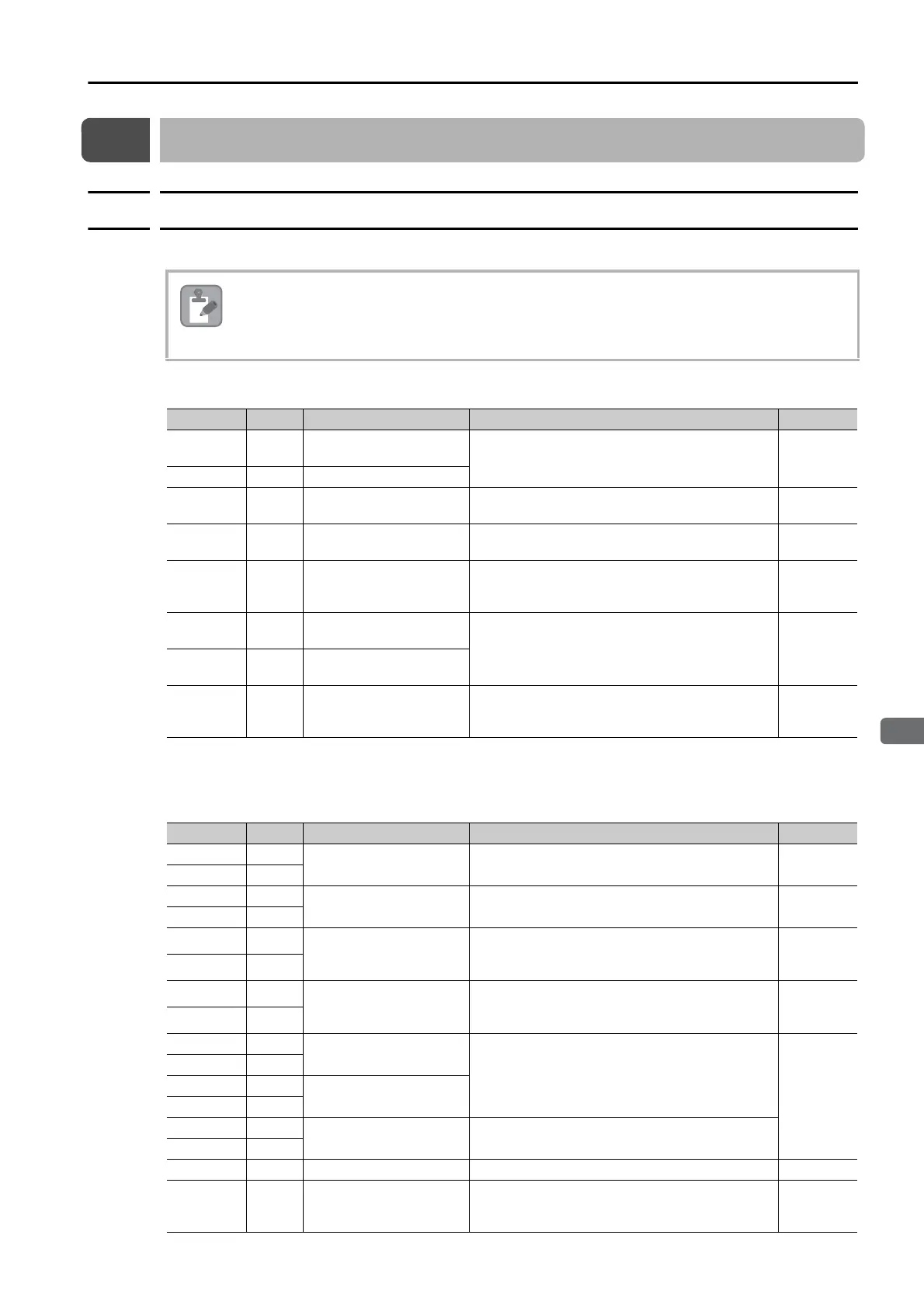
The following table gives the pin numbers, names, and functions of the I/O signal pins.
Input Signals
Note: If forward drive prohibition or reverse drive prohibition is used, the SERVOPACK is stopped by software con-
trols. If the application does not satisfy the safety requirements, add external safety circuits as required.
Output Signals
You cannot change the pin allocations for the I/O signals on CN1.
Signal Pin No. Name Function Reference
CCW-OT 8
CCW Drive Prohibit
Input
Stops Servomotor drive (to prevent overtravel)
when the movable part of the machine exceeds
the range of movement.
page 5-28
CW-OT 9 CW Drive Prohibit Input
/HOME 11 Origin Signal Input
Connects the deceleration limit switch for origin
return.
page 12-3
EXSTOP 12 External Stop Input
Stops Servomotor drive immediately and turns
OFF the servo in the SERVOPACK.
page 6-34
+24VIN
6
Sequence Input Signal
Power Supply Input
Inputs the sequence input signal power supply.
Allowable voltage range: 24 VDC ±20% The 24-
VDC power supply is not provided by Yaskawa.
−
BAT+
14
Battery for Absolute
Encoder (+)
These are the pins to connect the absolute
encoder backup battery.
Do not connect these pins if you use the
Encoder Cable with a Battery Case.
−
BAT-
15
Battery for Absolute
Encoder (-)
TH 5
Overheat Protection
Input
Inputs the overheat protection signal from a Lin-
ear Servomotor or from a sensor attached to
the machine.
page 6-35
Signal Pin No. Name Function Reference
ALM+ 3
Servo Alarm Output Turns OFF (opens) when an error is detected.
page 6-3
ALM- 4
/BK+ 1
Brake Output
Controls the brake. The brake is opened when
the signal turns ON (closes).
page 5-31
/BK- 2
/WARN+ 23
Warning Output
It remains ON continuously while a warning is
being detected.
page 6-3
/WARN- 24
/S-RDY+ 25
Servo Ready Output
This output is ON (closed) when the control
power supply and main circuit power supply are
ON and a servo alarm has not occurred.
page 6-4
/S-RDY- 26
PAO 17
Encoder Divided Pulse
Output, Phase A
Output the encoder divided pulse output sig-
nals with a 90° phase differential.
page 6-18
page 6-23
/PAO 18
PBO 19
Encoder Divided Pulse
Output, Phase B
/PBO 20
PCO 21
Encoder Divided Pulse
Output, Phase C
Outputs the origin signal once every encoder
rotation.
/PCO 22
SG 16 Signal ground This is the 0-V signal for the control circuits. −
FG Shell Frame ground
Connected to the frame ground if the shield of
the I/O Signal Cable is connected to the con-
nector shell.
−
 Loading...


