5.11 Holding Brake
5.11.2 /BK (Brake) Signal
5
Basic Functions That Require Setting before Operation
5-31
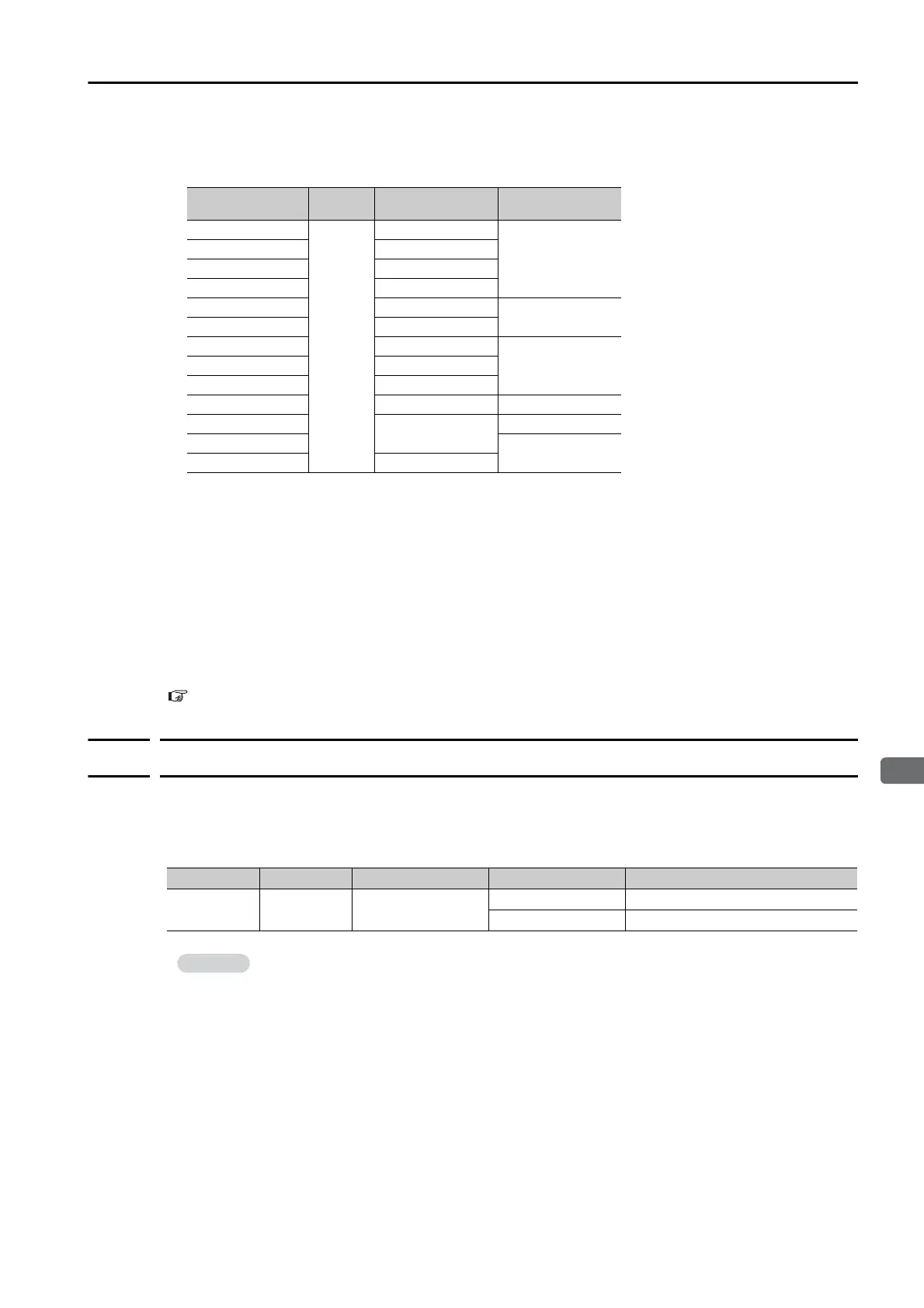
*1. Rotary Servomotors: The brake delay times for Servomotors with Holding Brakes are given in the following
table. The operation delay times in the following table are examples for when the power supply is switched on
the DC side. You must evaluate the actual brake delay times on the actual equipment before using the applica-
tion.
Linear Servomotors: The brake delay times depend on the brake that you use. Set the parameters related to
/BK signal output timing according to the delay times for the brake that you will actually use.
*2. Before you output a reference from the host controller to the SERVOPACK, wait for at least 50 ms plus the
brake release delay time after you send the Servo ON command.
*3. Use the following parameters to set the timing of when the brake will operate and when the servo will be turned
OFF.
• Rotary Servomotors: Pn506 (Brake Reference-Servo OFF Delay Time), Pn507 (Brake Reference Output
Speed Level), and Pn508 (Servo OFF-Brake Reference Waiting Time)
• Linear Servomotors: Pn506 (Brake Reference-Servo OFF Delay Time), Pn508 (Servo OFF-Brake Reference
Waiting Time), and Pn583 (Brake Reference Output Speed Level)
Connection Examples
Refer to the following section for information on brake wiring.
4.4.4 Wiring the SERVOPACK to the Holding Brake on page 4-32
5.11.2
/BK (Brake) Signal
The following settings are for the output signal that controls the brake.
The /BK signal is turned OFF (to operate the brake) when the servo is turned OFF or when an
alarm is detected. You can adjust the timing of brake operation (i.e., the timing of turning OFF
the /BK signal) with the servo OFF delay time (Pn506).
Model Voltage
Brake Release
Delay Time [ms]
Brake Operation
Delay Time [ms]
SGM7J-A5 to -04
24 VDC
60
100
SGM7J-06 and -08 80
SGM7A-A5 to -04 60
SGM7A-06 to -10 80
SGM7A-15 to -25 170
80
SGM7A-30 to -50 100
SGM7P-01 20
100SGM7P-02 and -04 40
SGM7P-08 and -15 20
SGM7G-03 to -20 100 80
SGM7G-30 to -44
170
100
SGM7G-55 to -1A
80
SGM7G-1E 250
Type Signal Connector Pin No. Signal Status Meaning
Output /BK CN1-1, CN1-2
ON (closed) Releases the brake.
OFF (open) Activates the brake.
The /BK signal will remain ON during overtravel. The brake will not be applied.
 Loading...


