4.3 Wiring the Power Supply to the SERVOPACK
4.3.3 Power ON Sequence
4-15
4.3.3
Power ON Sequence
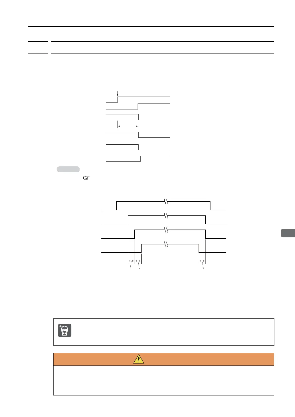
Consider the following points when you design the power ON sequence.
• The ALM (Servo Alarm) signal is output for up to five seconds when the control power supply
is turned ON. Take this into consideration when you design the power ON sequence, and
turn ON the main circuit power supply to the SERVOPACK when the ALM signal is OFF (alarm
cleared).
• If you use a DC power supply input with any of the following SERVOPACKs, use the power
ON sequence shown below: SGD7S-330A, -470A, -550A, -590A, or -780A.
• Design the power ON sequence so that main circuit power supply is turned OFF when an
ALM (Servo Alarm) signal is output.
• Make sure that the power supply specifications of all parts are suitable for the input power
supply.
• Allow at least 1 s after the power supply is turned OFF before you turn it ON again.
If the servo ON state cannot be achieved by turning ON the /S_ON signal, the /S_RDY signal
is not ON. Check the status of the /S_RDY signal. Refer to the following section for details.
/S-RDY (Servo Ready) Signal on page 6-4
Turn ON the control power supply and the main circuit power supply at the same time or turn ON
the control power supply before the main circuit power supply.
Turn OFF the main circuit power supply first, and then turn OFF the control power supply.
Even after you turn OFF the power supply, a high residual voltage may still remain in the
SERVOPACK. To prevent electric shock, do not touch the power supply terminals after you
turn OFF the power. When the voltage is discharged, the CHARGE indicator will turn OFF.
Make sure the CHARGE indicator is OFF before you start wiring or inspection work.
Up to 5.0 s
Control power supply
Main circuit power supply
ALM (Servo Alarm)
signal
/S_RDY (Servo Ready)
signal
/S-ON (Servo ON)
signal
Alarm cleared.Alarm
ONOFF
ONOFF
Motor power status
Power supplied.Power not supplied.
ONOFF
ONOFF
Power ON
Control power supply
ON
OFF
ONOFFMain circuit power supply
Motor power status
Power
not supplied. Power supplied.
Inrush current suppression
resistor switch
Switch: Open
Switch: Closed (Resistance connected.)
0.5 s min. Approx. 2 times switch
operating time according
to switch specications
Open switch 0.1 s or
longer after power is
not supplied to motor.
Important
 Loading...


