5.14 Electronic Gear Settings
5.14.1 Electronic Gear Ratio Settings
5-42
Calculating the Settings for the Electronic Gear Ratio
Rotary Servomotors
If the gear ratio between the Servomotor shaft and the load is given as n/m, where n is the
number of load rotations for m Servomotor shaft rotations, the settings for the electronic gear
ratio can be calculated as follows:
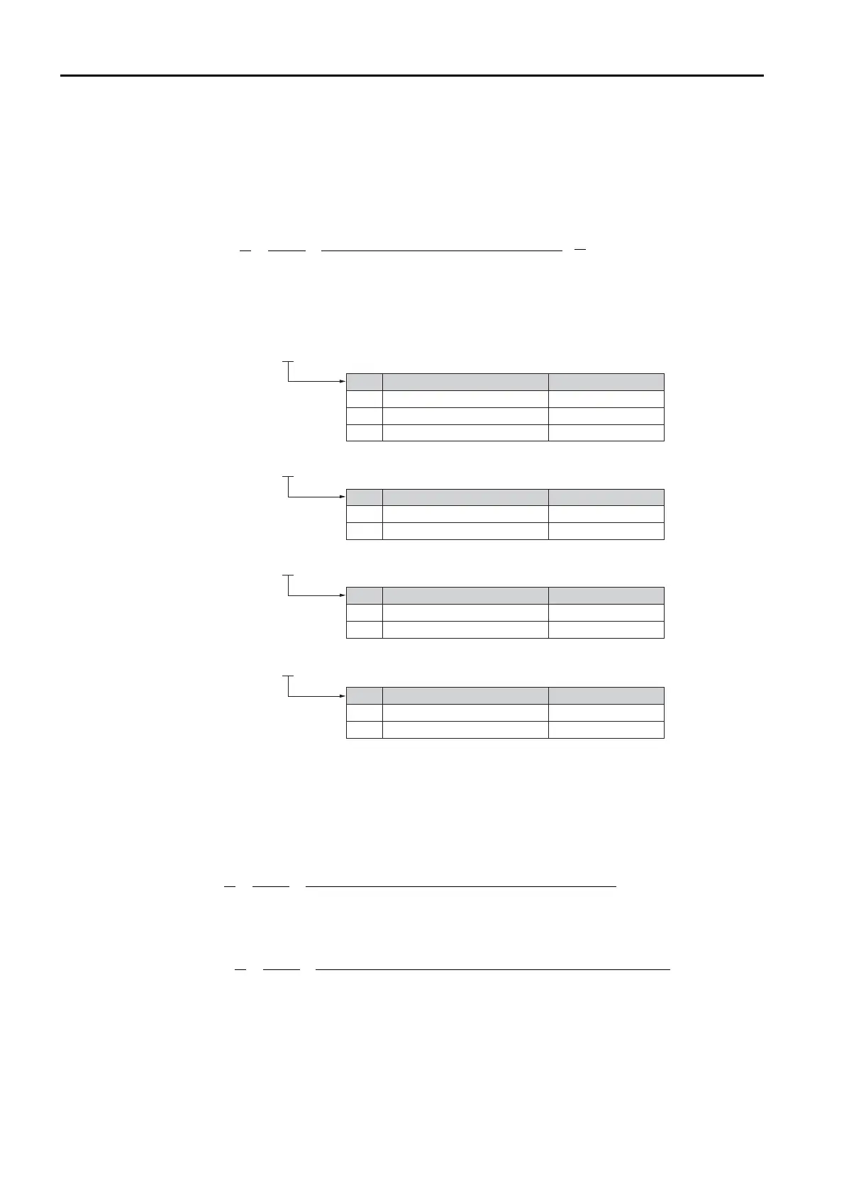
Encoder Resolution
You can check the encoder resolution in the Servomotor model number.
Linear Servomotors
You can calculate the settings for the electronic gear ratio with the following equation:
When Not Using a Serial Converter Unit
Use the following formula if the linear encoder and SERVOPACK are connected directly or if a
linear encoder that does not require a Serial Converter Unit is used.
When Using a Serial Converter Unit
==
×
B
A
Pn20E
Pn210
m
n
Electronic gear ratio
Encoder resolution
Travel distance per load shaft revolution (reference units)
6 16,777,216
SGM7J, SGM7A,
SGM7P, SGM7G -
7
16,777,216
F
16,777,216
SGMCS -
3
1,048,576
D
1,048,576
SGMCV -
E
4,194,304
I
4,194,304
SGM7E, SGM7F -
Code
Code
Code
Specication
Specication
24-bit multiturn absolute encoder
24-bit incremental encoder
20-bit single-turn absolute encoder
20-bit incremental encoder
Encoder Resolution
Encoder Resolution
Specication
22-bit single-turn absolute encoder
22-bit multiturn absolute encoder
Encoder Resolution
Code
Specication
24-bit batteryless multiturn absolute encoder
Encoder Resolution
7
16,777,216
F 16,777,216
24-bit multiturn absolute encoder
24-bit incremental encoder
Pn20E
Pn210
B
A
Electronic gear ratio
Travel distance per reference unit (reference units) × Linear encoder resolution
Linear encoder pitch (the value from the following table)
=
=
= =
Pn20E
Pn210
B
A
Electronic gear ratio
Travel distance per reference unit (reference units) × Resolution of the Serial Converter Unit
Linear encoder pitch (setting of Pn282)
 Loading...


