7.1 Flow of Trial Operation
7.1.2 Flow of Trial Operation for Linear Servomotors
7
Trial Operation and Actual Operation
7-3
7.1.2
Flow of Trial Operation for Linear Servomotors
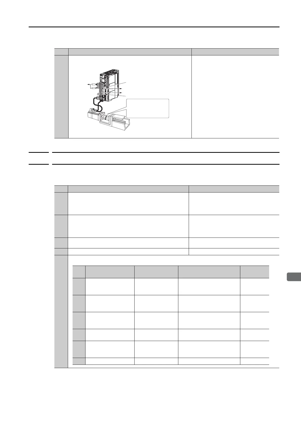
The procedure for trial operation is given below.
• Preparations for Trial Operation
3
Trial Operation with the Servomotor Connected to the
Machine
7.5 Trial Operation with the Servomotor Con-
nected to the Machine on page 7-11
Continued from previous page.
Step
Meaning Reference
To host controller
To power
supply
CN1
CN6
Secure the motor ange to the
machine, and connect the
motor shaft to the load shaft
with a coupling or other means.
Step
Meaning Reference
1
Installation
Install the Servomotor and SERVOPACK according to the
installation conditions. First, operation is checked with no
load. Do not connect the Servomotor to the machine.
Chapter 3 Installation
2
Wiring and Connections
Wire and connect the SERVOPACK. First, Servomotor
operation is checked without a load. Do not connect the
CN1 connector on the SERVOPACK.
Chapter 4 Wiring and Connections
3
Confirmations before Trial Operation
7.2 Inspections and Confirmations before Trial
Operation on page 7-6
4
Power ON −
5
Setting Parameters in the SERVOPACK
Continued on next page.
Step
No. of Parameter to
Set
Description Remarks Reference
5-1 Pn282
Linear Encoder
Pitch
Set this parameter only if
you are using a Serial Con-
verter Unit.
page 5-17
5-2 –
Writing Parameters
to the Linear Servo-
motor
Set this parameter only if
you are not using a Serial
Converter Unit.
page 5-18
5-3 Pn080 = n.X
Motor Phase
Sequence Selec-
tion
–
page 5-22
5-4 Pn080 = n.X
Polarity Sensor
Selection
–
page 5-24
5-5 – Polarity Detection
This step is necessary only
for a Linear Servomotor with
a Polarity Sensor.
page 5-25
5-6 Pn483, Pn484 Force Control –
page 6-17
 Loading...


