13.2 Communications Methods
13.2.1 I/O Communications
13
DeviceNet Communications
13-9
Switch to Positioning (Command Assembly Code = 0x1F)
This command code switches from continuous operation to positioning. This data is enabled
when the Valid Data bit is set to 1. The end position in PnB55 is used as the target position.
Set bytes 4 to 7 of the command data to 0x00.
This command is enabled only when the 15th bit of the action definition settings in PnBA5 is
set to 1. If the 15th bit of PnBA5 is cleared to 0, sending a Positioning command during contin-
uous operation will change to positioning operation. In that case, the target position is specified
in the command data.
Refer to the following section for information on switching to positioning.
13.3.4 Switching to Positioning on page 13-18
Response Format
This section describes the response messages from the SERVOPACK to the master device.
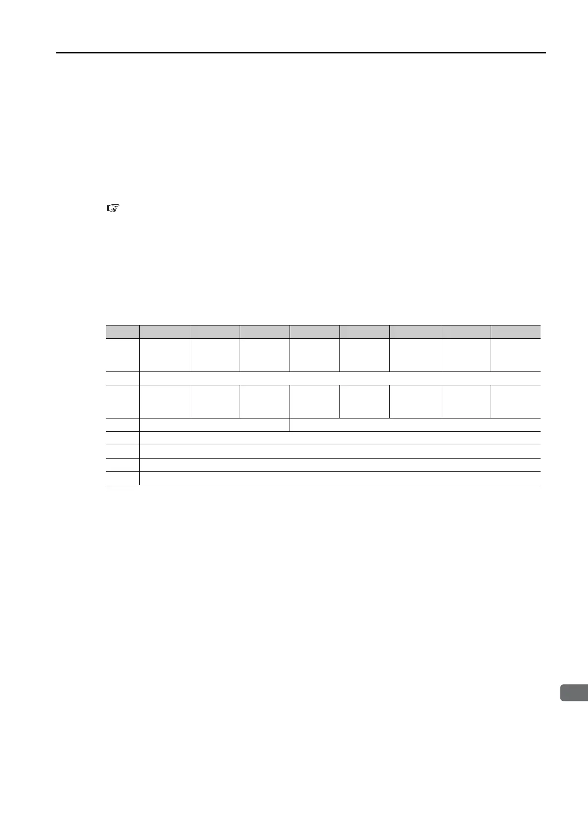
The following table gives the data format of the response messages that are sent from the
SERVOPACK to the master device. A response message consists of 8 bytes. Bytes 0 to 3 have
the same format for all commands that are sent from the master device. Byte 0 and byte 2
show the status of the SERVOPACK in bits. Bytes 4 to 7 store data that depends on the
response assembly code in byte 3.
Trajectory In Progress
This bit is set to 1 during positioning, continuous operation, or origin returns. The Trajectory In
Progress bit is set to 1 when operation starts after the Valid Data and the Start Trajectory bits
are set to 1 in the data from the master device. The bit is cleared to 0 when the operation is
completed.
Block In Execution
This bit is set to 1 during the execution of block commands for the Start Block bit. It is cleared
to 0 when the block commands have been completed or when block error occurs (as shown by
the Block Fault bit).
On Target Position
This bit is set to 1 when the current position is within the positioning completed width. The
value of PnB50 (Positioning Completed Width) is used as the positioning completed width.
Alarm
This bit is set to 1 if an alarm occurs in the SERVOPACK. Use the Alarm Clear command to
clear the alarm.
External Stop Input
This bit is used to monitor the external stop input signal of the SERVOPACK. This bit is set to 1
when the external stop input signal is active.
Bytes Bit 7 Bit 6 Bit 5 Bit 4 Bit 3 Bit 2 Bit 1 Bit 0
0
Enable
State
Valid
Data
Home
Flag
External
Stop
Input
Alarm
On
Target
Position
Block
In
Execution
Trajectory
In
Progress
1 Executing Block Number
2
Com-
mand
Error
Block
Fault
Trajectory
Start
Echo
Negative
Software
Limit
Positive
Software
Limit
CCW
Hardware
Limit
CW
Hardware
Limit
Servo
Ready
3 Axis Instance Response Assembly Code
4 Data Low Byte
5 Data Low Middle Byte
6 Data High Middle Byte
7 Data High Byte

 Loading...


