13.3 Controlling Operation from the Host Controller
13.3.3 Origin Returns
13
DeviceNet Communications
13-17
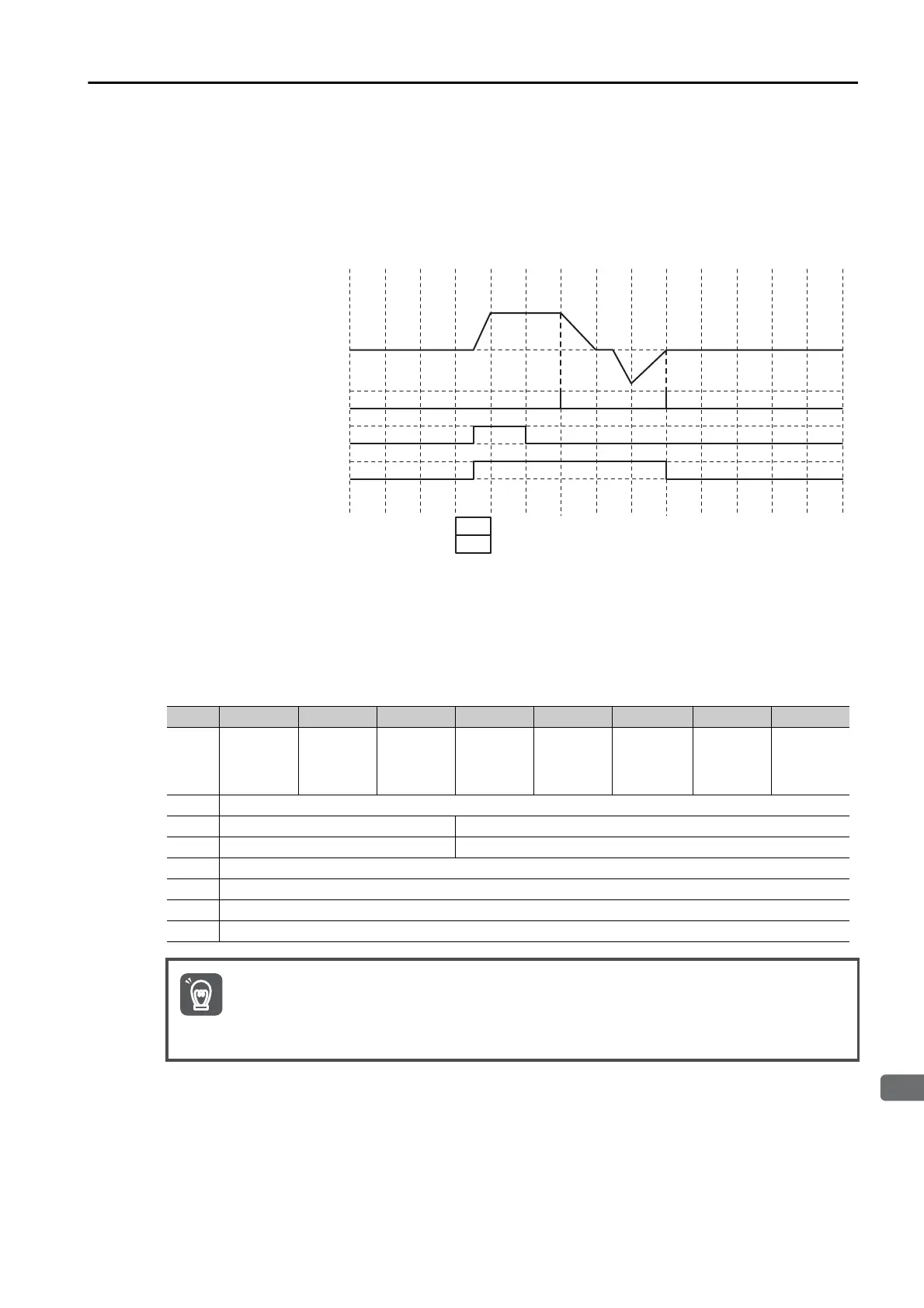
Typ e 3
Origin returns are based only on the detection of phase C of the encoder.
1.
The axis travels at the origin approach speed in the specified origin return direction.
2.
When the first phase C is detected, the axis will stop, reverse direction, and travel to the
position where phase C was detected.
Origin Return Operation Example
An example of a command message for an origin return is given in the following table. A type 0
origin return is used in this example. The SERVOPACK assumes that the data, such as the
Start Trajectory bit, is valid when the Valid Data bit in the command message is set to 1. There-
fore, set bytes 1 to 7 first, and then set byte 0.
Bytes Bit 7 Bit 6 Bit 5 Bit 4 Bit 3 Bit 2 Bit 1 Bit 0
0
1
Enable
1
Valid
Data
0
Hard
Stop
0
Smooth
Stop
0
Direction
(V mode)
0
Absolute/
Incremen-
tal
0
Start
Block
1
Start
Trajectory
1 0x00 Block Number
2 0x1 Axis Instance 0x12 Command Assembly Code
3 0x1 Axis Instance 0x03 Response Assembly Code
4 0x00 (Homing Type)
5 0x00
6 0x00
7 0x00
• If an alarm occurs, the servo is OFF, or another operation command, such as positioning or an
origin return, is being executed, the origin return command will be ignored.
• Make sure that the Enable State bit in the response message is set to 1, and then set the Start
Trajectory bit. If you set the Enable bit and the Start Trajectory bit at the same time, the Start
Trajectory bit will be ignored.
Motor speed
Encoder’s phase C signal
0
1
0
1
0
1
Command Assembly Code
Command Data
Start Trajectory
Trajectory In
Progress
12h
A1
A1
V1
D1
D1
03h
 Loading...


