2N® EasyGate IP User Manual
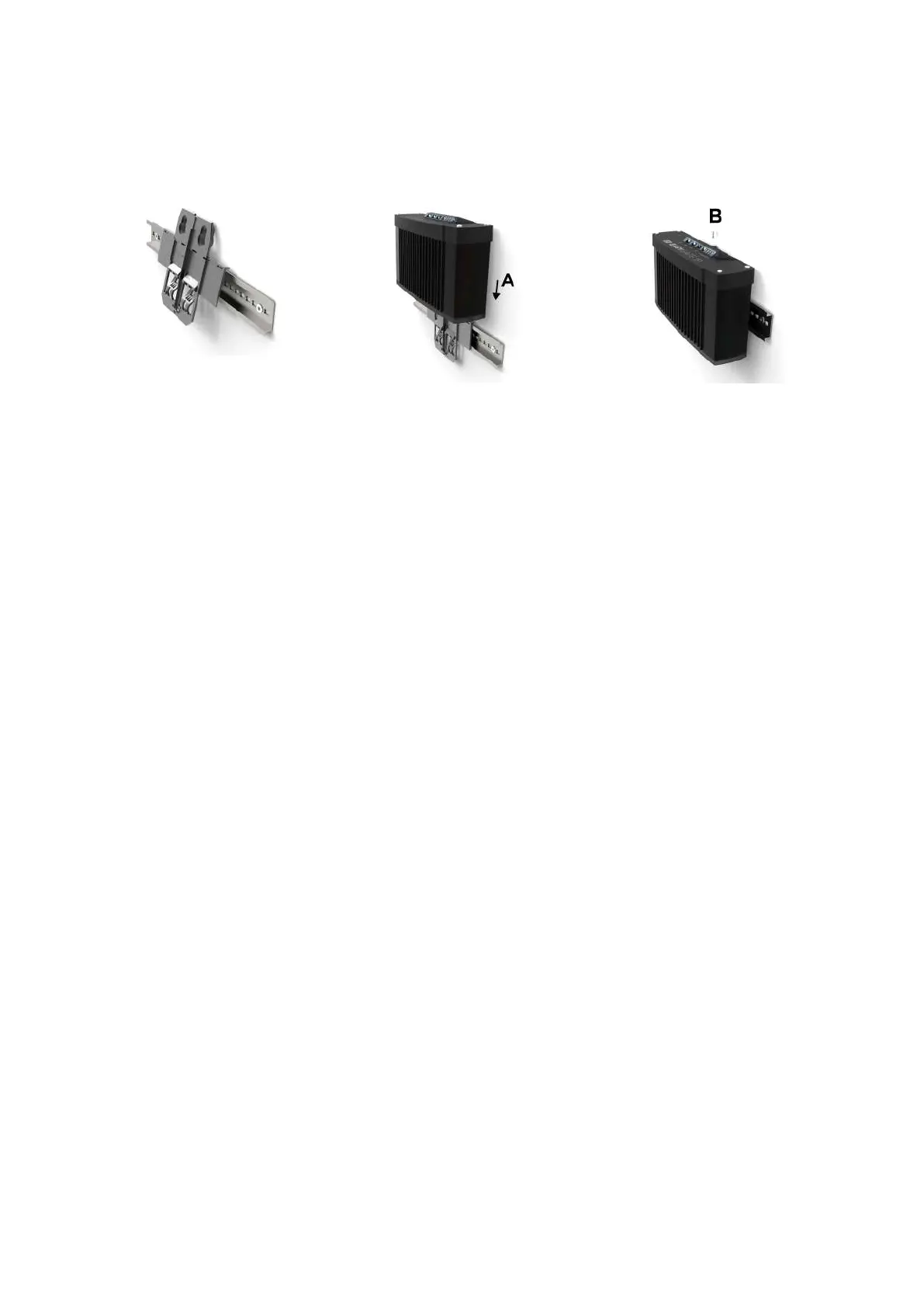
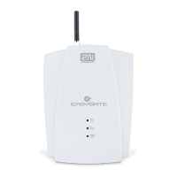
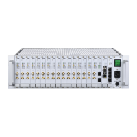
DIN Rail Mounting
No other tool is needed for DIN rail installation. The DIN rail bracket has a standard size of 35
mm. Put the upper inner side of the bracket profile on the DIN rail and push its bottom side to
make the bracket click and fit to the DIN rail.Now all you have to do is slide 2N
®
EasyGate IP
from the top into the bracket profile (A) and fit its position with a screw (B).
Wall Installation
Use the bracket and two dowels with screws included in the package to install 2N
®
EasyGate IP
on a wall. Drill holes in a selected place and selected height of the wall and insert the dowels.
Pass the screws through the bracket holes and screw them into the dowels in the wall. Now all
you have to do is slide 2N
®
EasyGate IP from the top into the bracket profile (A) and fit its
position with a screw (B).
2.3 Electric Installation
2N
®
EasyGate IP consists of a VoIP gateway in a black case, removable antenna and phone / PC /
power supply connecting cables.
To put 2N
®
EasyGate IP in operation, connect the device to the power supply, connect an
external antenna and insert the SIM card.
Device Connection to Power
Connect the supplied power terminals to the POWER connector, connect the power supply to
the mains. The device activity is signaled by status LED indicators. Refer to Subsection 2.5
Overview of LED Indicators for details. 2N
®
EasyGate IP is fed with DC 9–30 V / 1 A via a supply
cable.Where a source other than the included power supply is used, the allowed voltage range
and polarity have to be maintained according to the technical parameters. AA batteries with the
minimum contact height of 1.7 mm are only recommended.
In the case of a power failure, four NiMH size AA (1.2 V / min. 2000 mAH) batteries inside the
device provide power backup and thus normal operation of the device. As part of the device, this