05 MECHANICAL INSTALLATION
3BHS212794 E01 REV M ACS6000 USER MANUAL 116/278
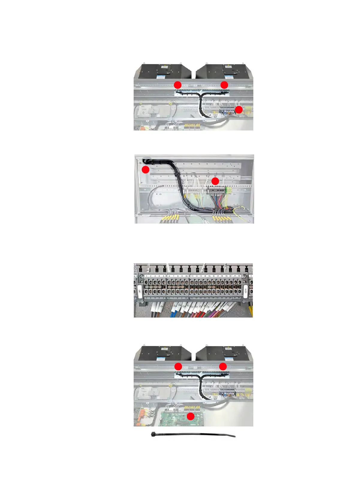
8. From the openings (1), route the cables to the terminals (2) as
illustrated in the examples for ARU / INU / IFU 9 MVA and LSU.
Figure 5-12 ARU/INU/IFU cable routing
Figure 5-13 LSU cable routing
9. Connect each wire to terminal block -X1 according to the terminal
numbers printed on the marker sleeves (white).
10. In the upper part of the cable duct (1), fasten the cables to the
cabinet frame.
11. In the lower part (2), tie the cables together at regular distances.
1 1
2
1
2
2