3BHS212794 E01 REV M ACS6000 USER MANUAL 129/278
06 ELECTRICAL INSTALLATION
6.3 Grounding the drive system
To identify the ground buses, see “Appendix C – Mechanical drawings”.
6.3.1 Grounding diagrams
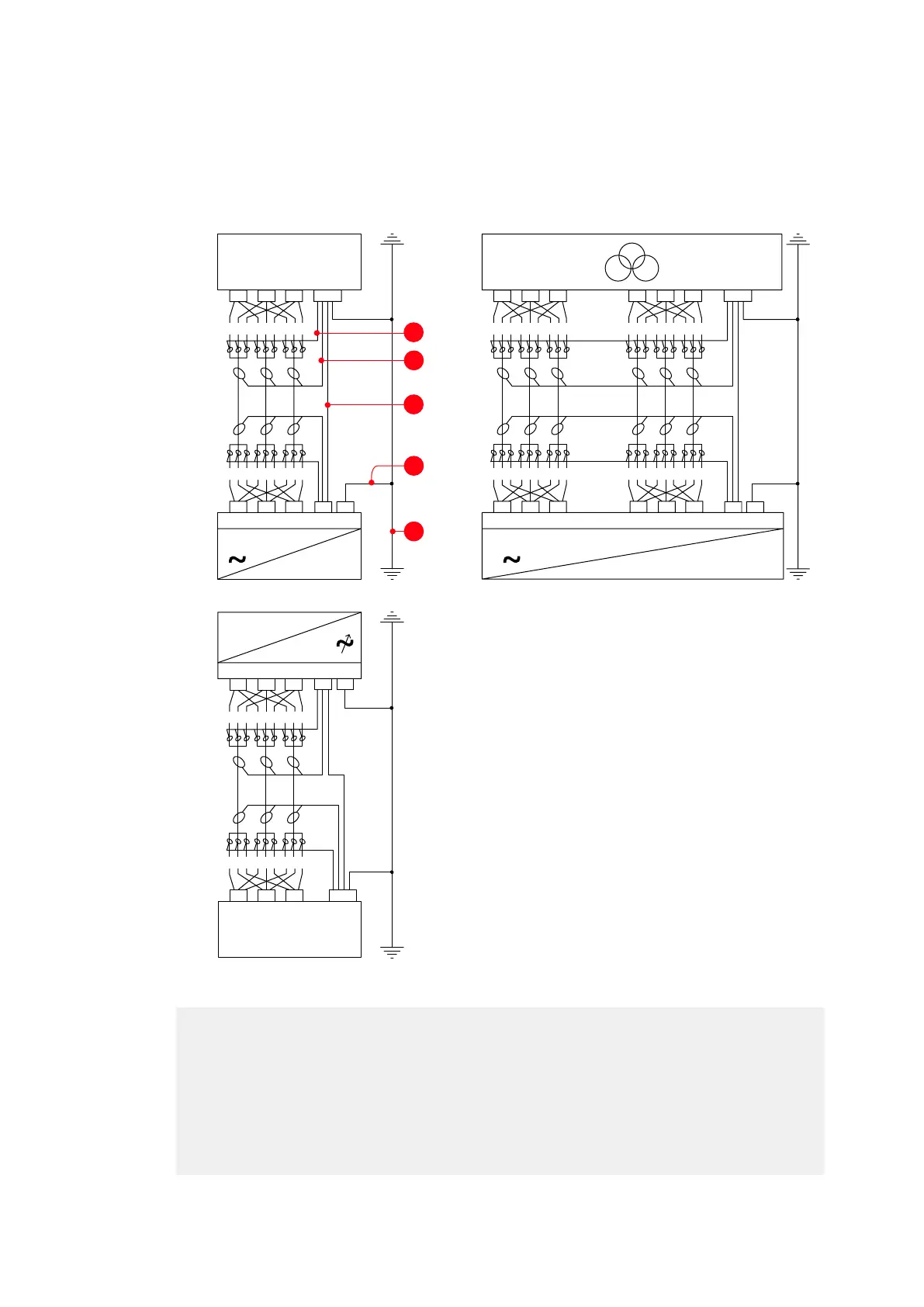
Figure 6-2 Grounding the input side (A) and output side (B) of the drive system
(1) Transformer or busbar
(2) System ground
(3) Cable shield
(4) Cable armor
(5) Equipotential bonding conductor
(6) Ground cable
(7) TEU
(8) ARU
(9) Transformer
(10) LSU
(11) INU
(12) Motor
==
L1
L2 L3
PEU1 V1 W1
PG PE
=
123 123 123
123 123 123
12
L1
L2 L3
PE
3123123
123 123 123
L1
L2 L3
PG PE
L1 L2 L3 2L1
2L2 2L3
PG PE
U1 V1 W1
PE
U2 V2 W2
123 123 123 123 123 123
123 123 123 123 123 123
A
B
1
3
5