08 OPERATION
3BHS212794 E01 REV M ACS6000 USER MANUAL 176/278
8.4.2.1 Lamp test
The illuminated push buttons on the doors can be tested with the lamp
test function as described in the firmware manual, see “Appendix G –
Signal and parameter table”.
8.4.3 Semi-redundant drive control panel (drive backup control)
The semi-redundant drive system applies to single drives with an even
number of inverter units.
A semi-redundant drive system consists of the following features:
• One single-motor drive with double or quadruple inverter units for
one common motor.
• One common control unit for the whole drive system.
• Transfer between full- and half-power is not bumpless.
• Line disconnectors are provided in the inverter units to separate
the inverters from the motor.
Note: The configurations shown here are typical examples. Different
configurations are possible. The optional ISU can be used to split up the
drive lineup in half-power mode by opening the DC link.
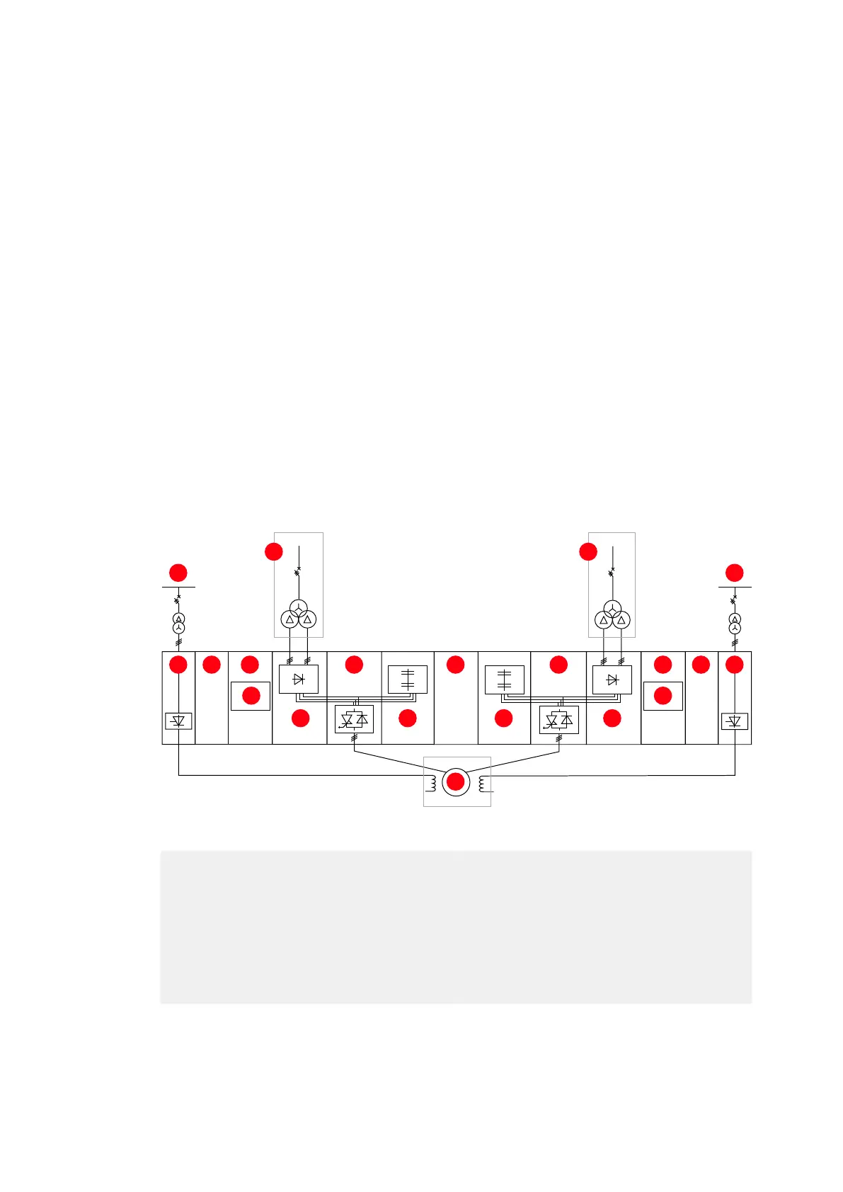
Figure 8-3 Typical semi-redundant drive configuration
(1) Excitation power
(2) Mains
(3) EXU
(4) WCU
(5) COU
(6) Control
(7) LSU
(8) INU
(9) CBU/RBU
(10) ISU
(11) Motor
1 1
2 2
3 344 5 5
6 6
7 7
8 8
9 9
10
11