4Installation
Hardware Installation
2D-LC User Guide 84
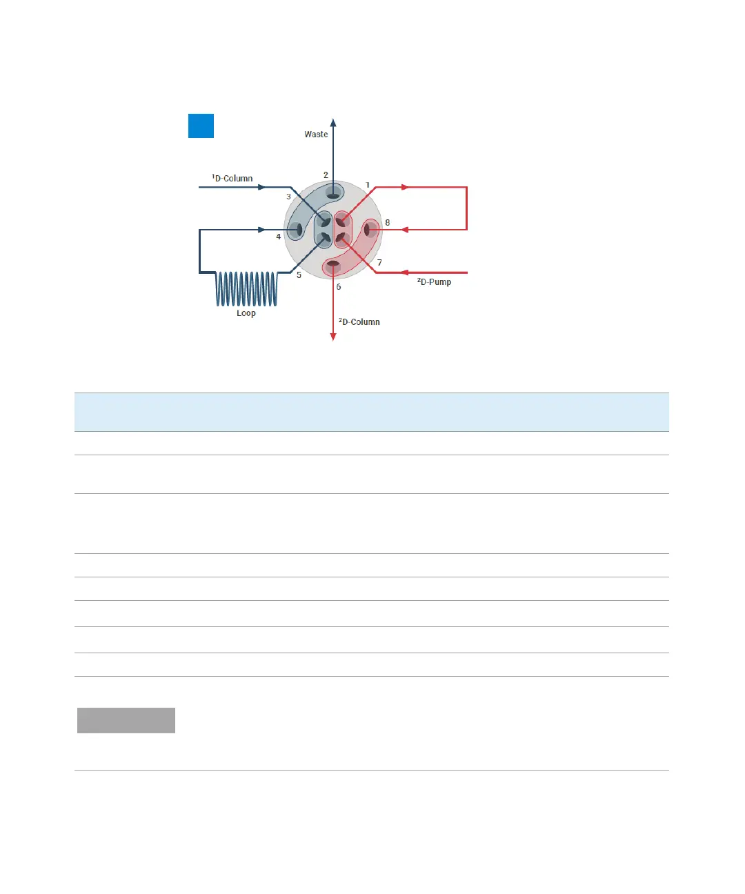
Figure 40 Setup G. Single Heart-Cutting Configuration as Single Sample Loop Setup
Number of
Capillary
# Connection ID x L [mm] P/N Description
1 1 Bypass capillary (OUT) 0.12 x 10⁵ 5500-1238 Capillary, ST 0.12x10⁵ SL/SL
2 1 Waste line self-cut x 0.7 0890-1713 Tubing-flexible 0.8/1.61mm PTFE
WT (delivered with UV detector)
3 1 From pressure release kit; from
1
D column,
1
D detector
0.17 x 10⁵
0.12 x 500
5500-1240
5500-1157
Capillary ST 0.17x10⁵ SL/SL
Capillary ST 0.12x500 SL/S
4 Sample Loop (IN) 5004-0036 180 µL Loop 2D-LC as an example
5 Sample Loop (OUT) 5004-0036 180 µL Loop 2D-LC as an example
61
To
2
D column
0.12 x 400 5500-1251 Capillary ST 0.12x400 SL/SL
71
From
2
D pump
0.17 x 280 5067-4608 Capillary ST 0.17x280 SX/S
8 Bypass capillary (IN) 0.12 x 10⁵ 5500-1238 Capillary, ST 0.12x10⁵ SL/SL
For all other capillaries / connections, see Figure 31 on page 73, Figure 32 on page 74, and Figure 33 on page 75.
If the dual-loop setup has been selected in the software configuration (see “Configure the 2D-LC Cluster” on page 96),
install mirror-inverted, the sample loop at port 1 and 8 and the bypass capillary at position 4 and 5.

 Loading...


