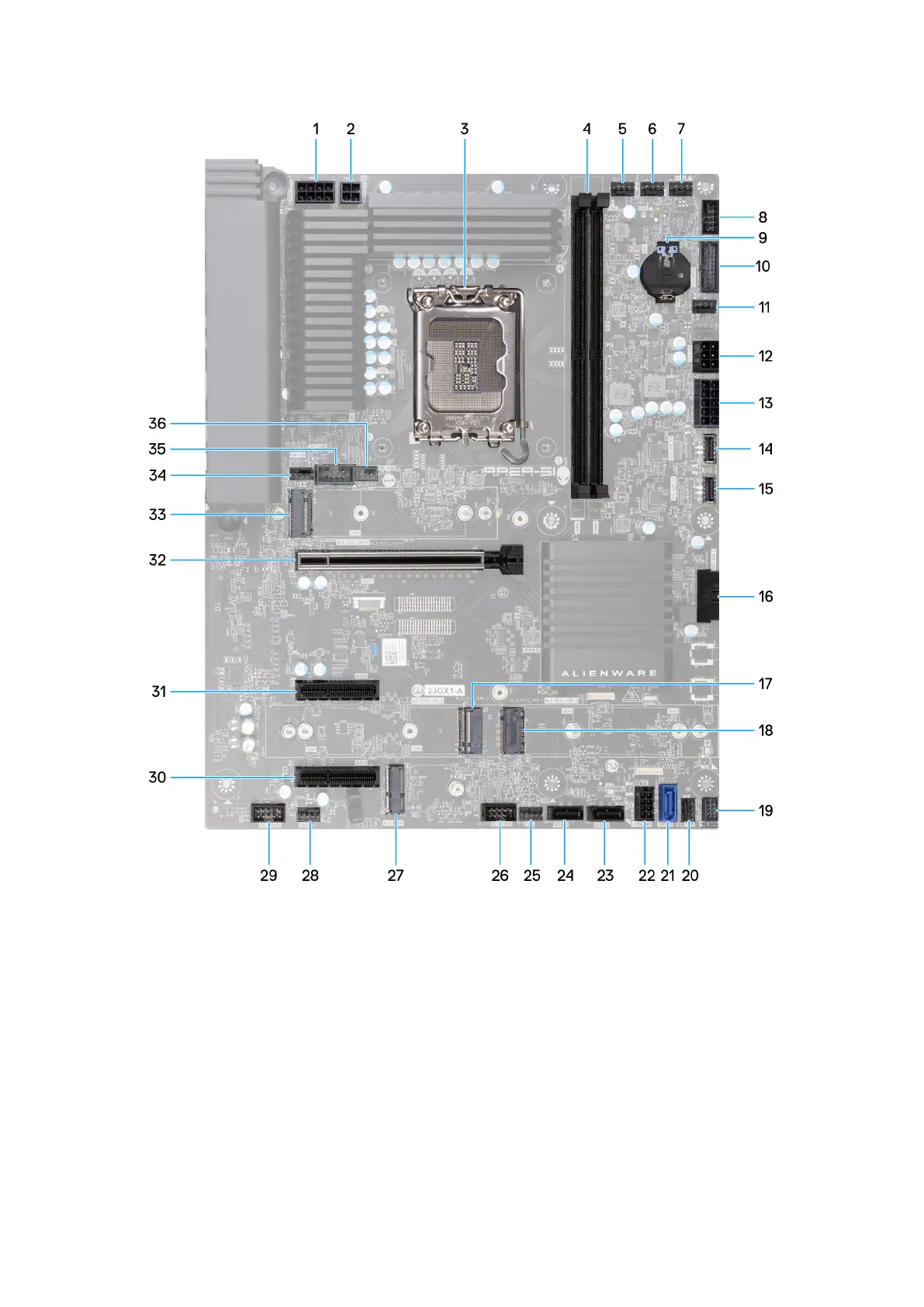
Figure 123. System-board connectors
1. Power-supply connector (ATX CPU1)
2. Power-supply connector (ATX CPU2)
3. Processor socket
4. Memory module (DIMM1 and DIMM2)
5. Top-fan assembly cable connector (FAN1)
6. Top-fan assembly cable connector (FAN2)
7. Top-fan assembly cable connector (FAN3)
8. 9-pin USB header
9. Coin-cell battery socket (RTC)
10.AlienFX data connector (ELC_DATA1)
11. Front-fan connector (FAN4)
12. Power-supply connector (ATX AUX)
13. Power-supply connector (ATX SYS)
Removing and installing Field Replaceable Units (FRUs) 137