Installation
J K
'~
~/
ABC
D E F G H
AIR
~
I
FLOW.,.!
4
.r----.:.:'--'
/
EXHAUST AIR FLOW
r-l
t
MAXIMUM LENGTH
OF
DUCT
-lJl
61
em (24 In.)
9.1
m (30 ft.) MINIMUM
EXHAUST CLEARANCE
TO
OUTLET ROOF/GROUND
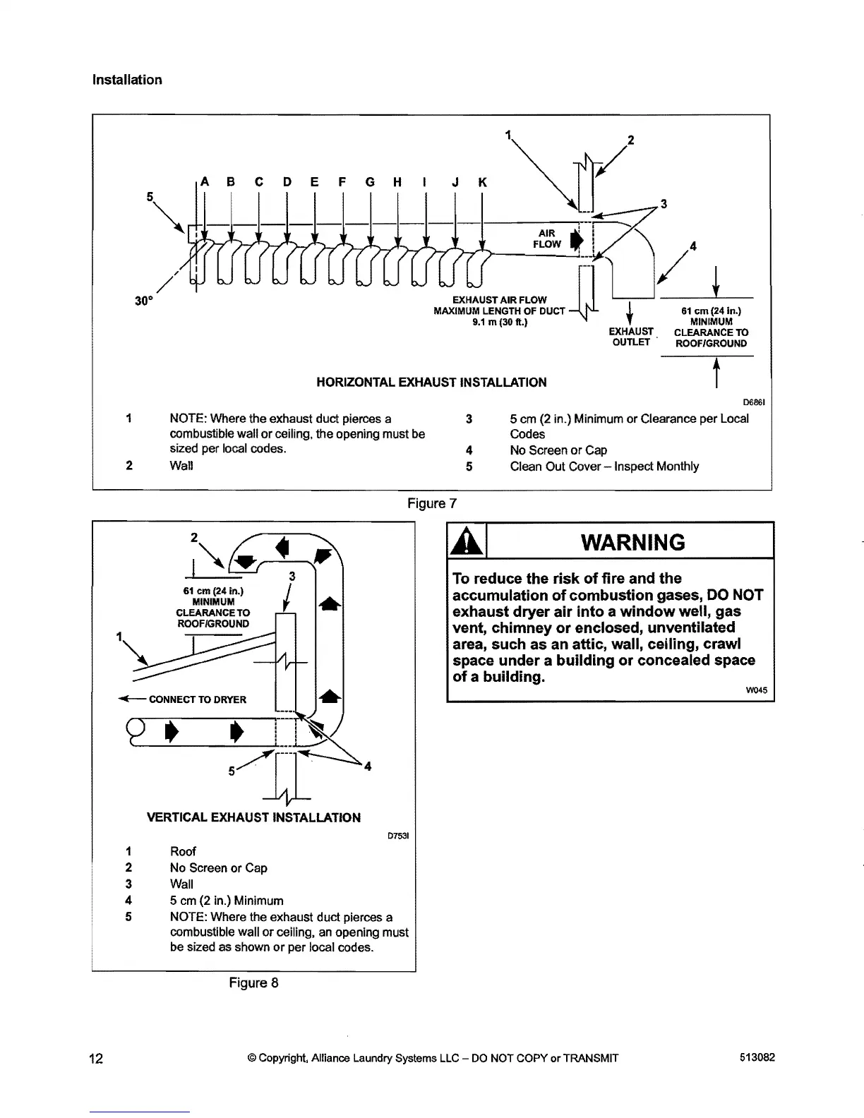
HORIZONTAL EXHAUST INSTALLATION
t
06861
1 NOTE: Where the exhaust duct pierces a
3
5 cm (2 in.) Minimum or Clearance per Local
combustible wall
or
ceiling, the opening must be
Codes
sized per local codes.
4
No Screen
or
Cap
2
Wall
5
Clean Out Cover
-Inspect
Monthly
Figure 7
1
2
l~
61
em (24 In.)
MINIMUM
CLEARANCE TO
ROOFIGROUND
..
~
CONNECT TO DRYER
..
4
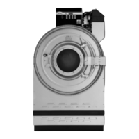
VERTICAL EXHAUST INSTALLATION
D7531
1 Roof
2 No Screen or Cap
3
Wall
4 5
em
(2 in.) Minimum
5 NOTE: Where the exhaust duct pierces a
combustible
wall
or
ceiling,
an
opening must
be sized as shown
or
per local codes.
WARNING
A.I
To
reduce the risk
of
fire and the
accumulation
of
combustion gases,
DO
NOT
exhaust dryer
air
into
a
window
well, gas
vent, chimney
or
enclosed, unventilated
area, such as an attic, wall, ceiling, crawl
space under a building
or
concealed space
of
a building.
W045
Figure 8
12
© Copyright, Alliance Laundry Systems LLC
DO
NOT COPY or TRANSMIT
513082