Coupling and uncoupling the machine
7.1.1 Hydraulic connections
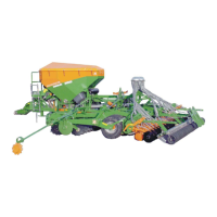
• All hydraulic hose lines are equipped with grips.
Coloured markings with a code number or code letter have been
applied to the gripping sections in order to assign the respective
hydraulic function to the pressure line of a tractor control unit!
Films are stuck on the implement for the markings that illustrate
the respective hydraulic function.
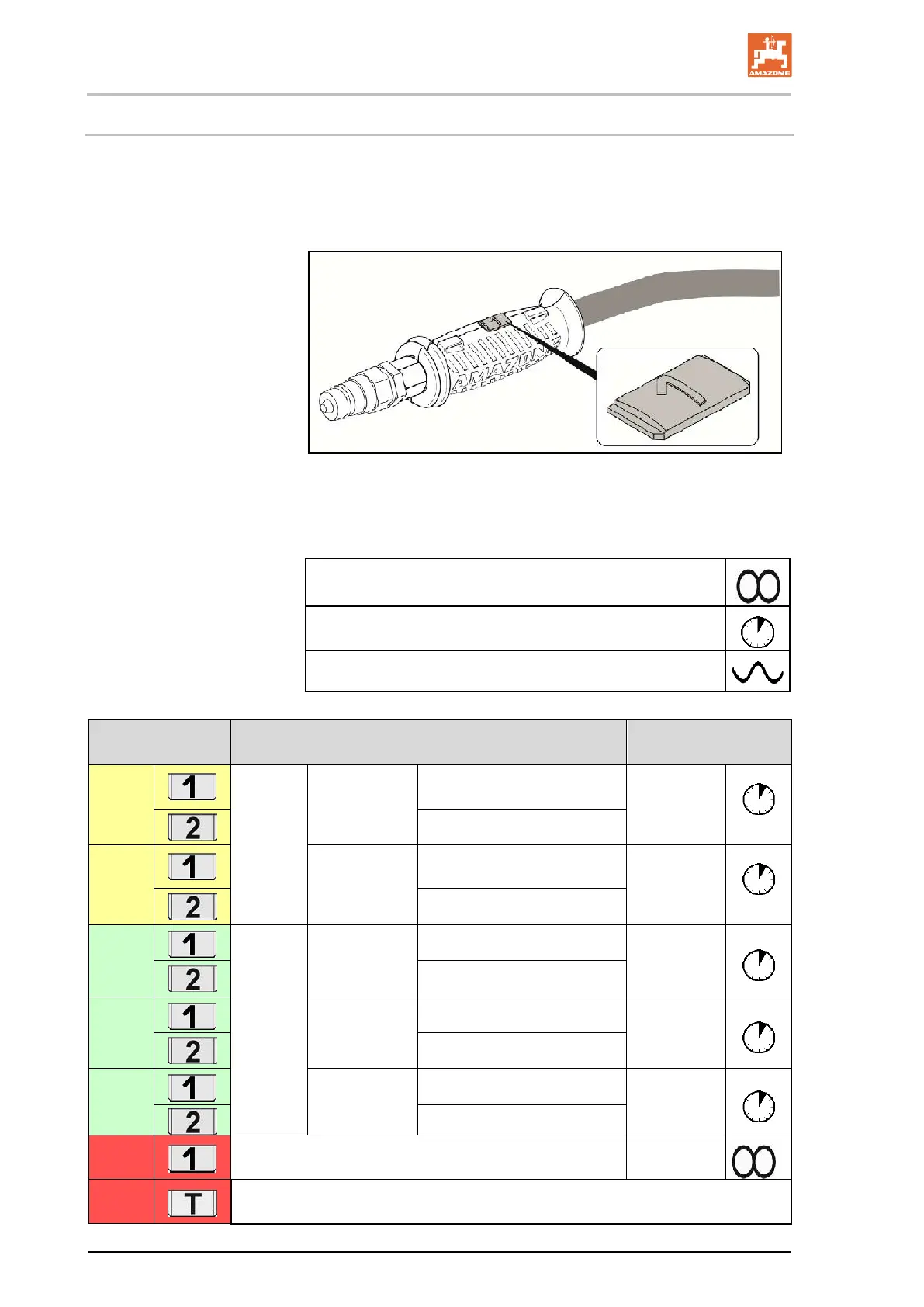
• The tractor control unit must be used in different types of activa-
tion, depending on the hydraulic function.
Latched, for a permanent oil circulation
Tentative, activate until the action is executed
Float position, free oil flow in the control unit
Marking Function Tractor control unit
yellow
Pre-
selection
via
switch tap
Running gear /
track marker /
pre-emergence
marker
Put in working position
Double-
acting
Put headlands position
yellow
Turning on the
roller
Lowering the coulter frame/ disc
array
Double-
acting
Lifting the coulter frame / disc
green
Pre-
selection
via
switch tap
machine exten-
sion arms
Fold out
Double-
acting
Fold in
green
exact harrow
coulter pres-
sure
Increase
Double-
acting
Decrease
green
Disc array
depth adjust-
ment
Increase
Double-
acting
Decrease
red
Hydraulic fan motor
Single-
acting
red
Pressure-free return flow
108 Cirrus BAH0049-1 09.14
 Loading...