INSTALLATION
iKon-L SECTION 2
Page 31
2.3 - INSTALLING THE HARDWARE
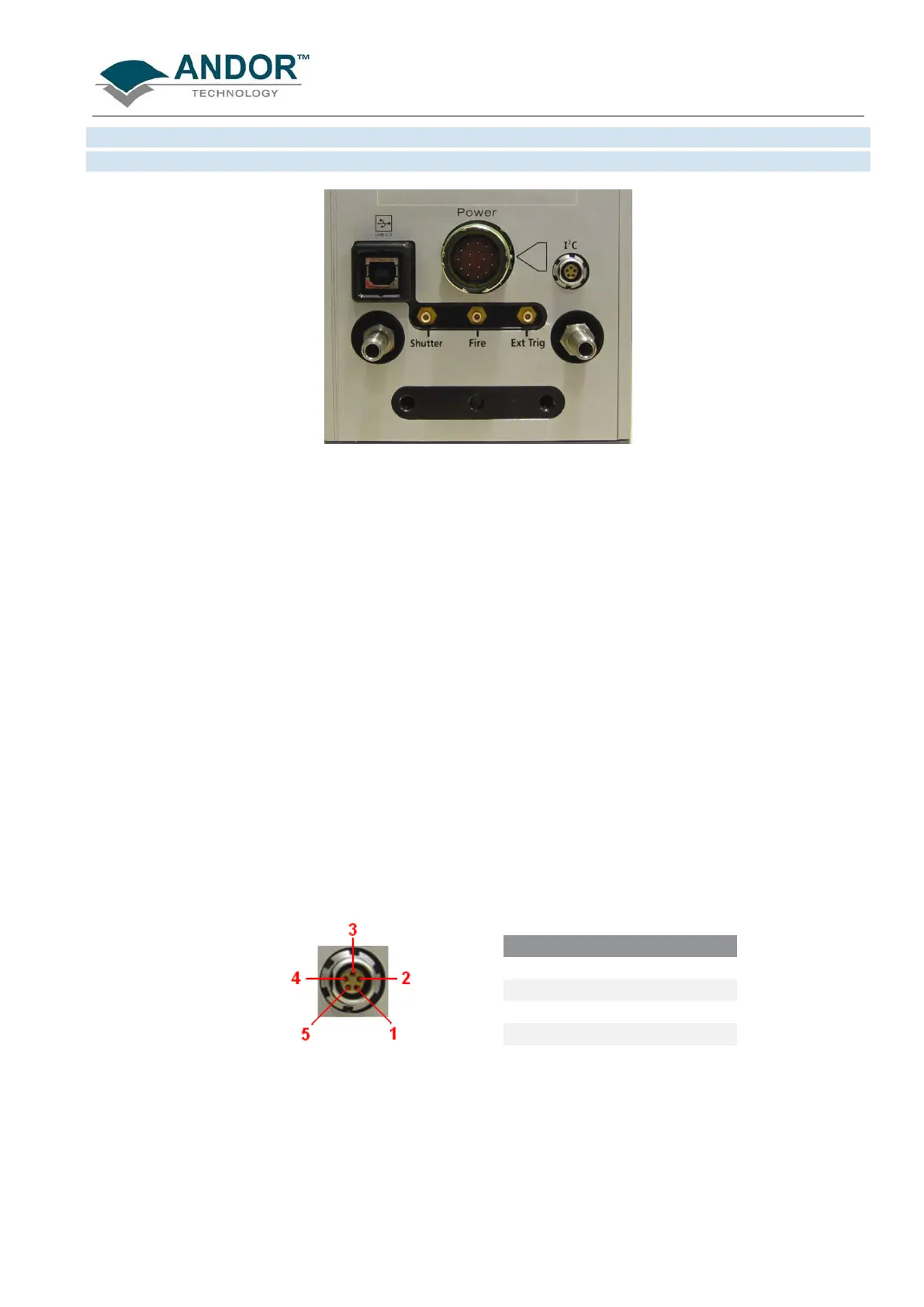
Figure 10: iKon-L rear connectors
There are 6 connection points on the rear of the iKon-L as shown above.
Three of the connectors are industry-standard SMB (SubMiniature B) connectors which are labelled from left to
right as follows:
• Shutter
• Fire
• Ext Trig
These are used to send or receive Triggering and Firing signals, which are described later in this manual. The
SMB outputs (Fire & Shutter) are CMOS compatible & Series terminated at source (i.e. in the camera head)
for 50Ω cable. NOTE: The termination at the customer end should be high impedance (not 50Ω) as an
incorrect impedance match could cause errors with timing and triggering.The SMB Ext Trig input is TTL
level & CMOS compatible and has 470Ω impedance.
The other rear connections are as follows:
• USB 2.0: a USB 2.0 compatible cable can be connected between this connector and a PC.
• I
2
C: Philips
™
introduced the I
2
C
™
bus 20 years ago and today it is the de facto standard for controlling
and monitoring applications in computing, communications and industrial segments.
connections for the 5-way I
2
C socket used on the iKon-L are shown below:
Figure 11: I
2
C connection (facing in) with pinouts
PIN FUNCTION
1
SHUTTER (TTL)
2
I
C CLOCK
3
I
C DATA
4
+5V
5
GROUND
• Power: the 16-pin socket is used to connect the PS40 Power Supply Unit cable (see page 18 for
further details).
 Loading...