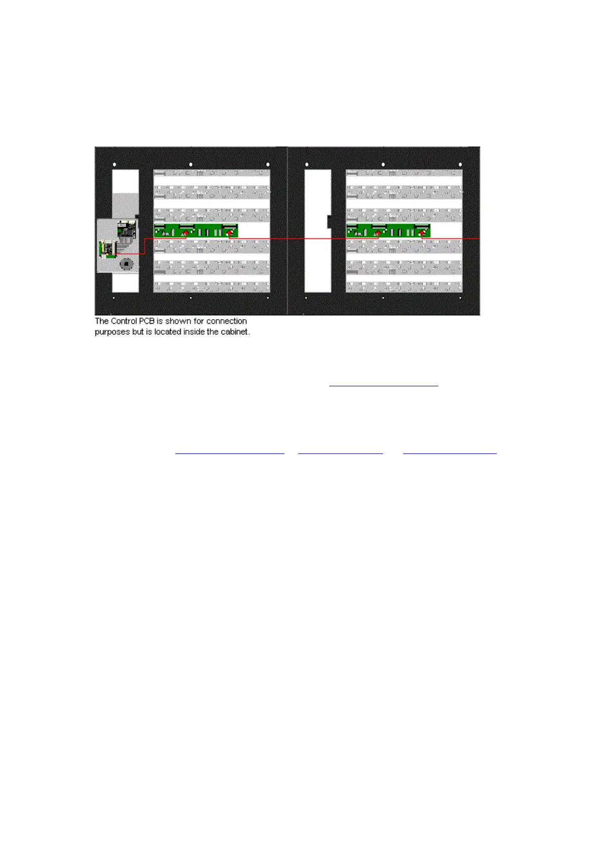
NOTE: Cables running between systems must be passed through the cut-outs in the sides of the
cabinets. If no cut-out exists (older systems), a suitable size hole must be cut in the side of the
cabinet. Cables must not be passed behind the cabinet as they could be damaged when trapped
against the wall.
3. If you have more extension cabinets then continue to connect the Output to Input of the remaining
Interface PCBs.
NOTE: When connecting the Interface PCBs it is important to check the following...
Cabinet Selector settings. Please refer to the Interface Selector Settings section of the Traka32
Help Guide for details on the correct settings.
Cabinet Jumper settings. Please check there is only a link across the J1 jumper on the last cabinet
in the series. All the other cabinets must not have the link across J1.
Please refer to the 8bit Control PCB Diagrams or 16bit I/O PCB layout and Interface PCB Diagram of the
Traka32 Help Guide to locate the various connections.