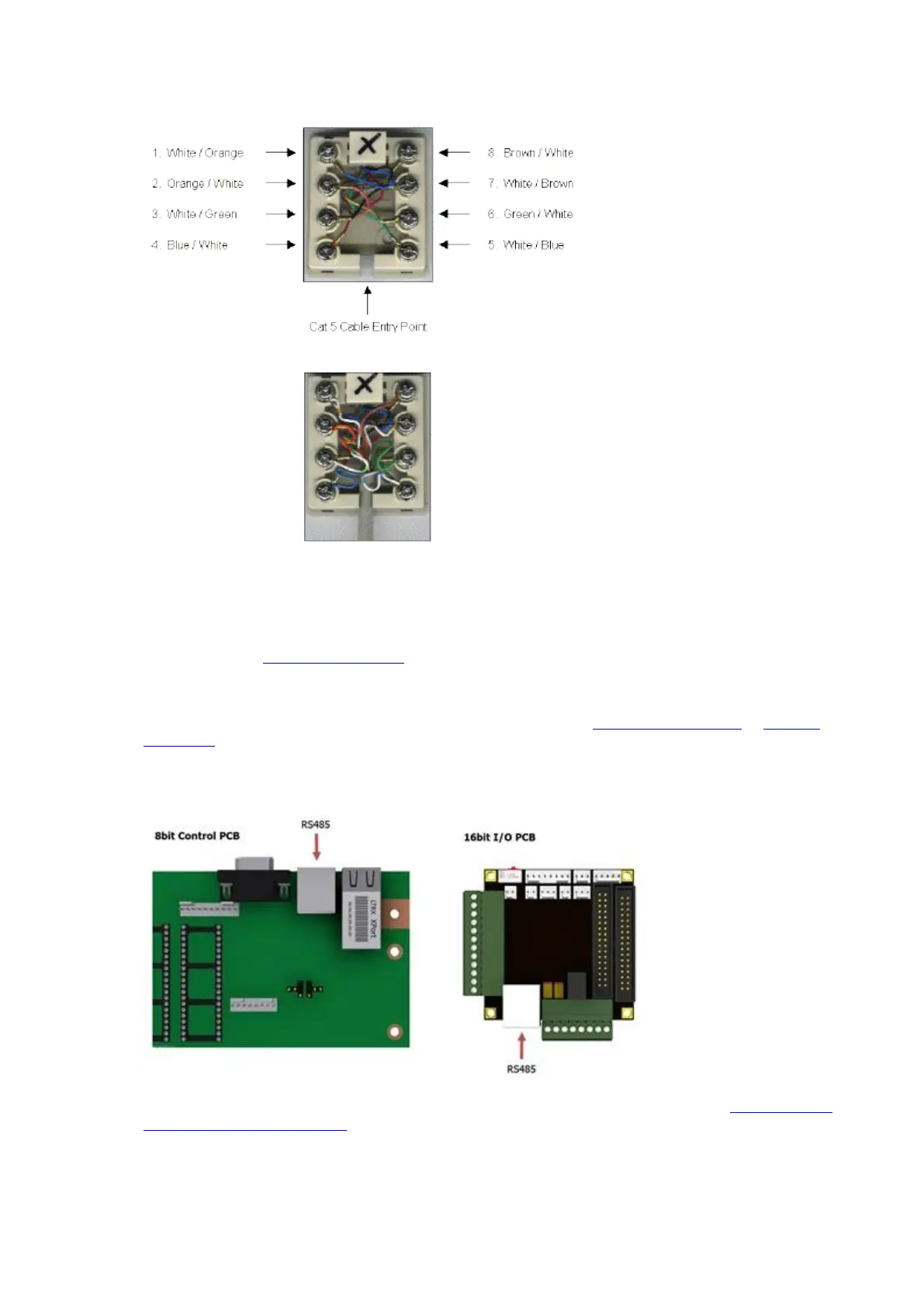
4. Connect as follows...
5. When all the connections are made, place the cover over the RJ45 Wall Port and connect the Traka and PC
Patch Cables. Refer to the Configuration and Connection section below.
Configuration and Connection
1. Please refer to the Anti Static Precautions before configuring the Traka systems.
2. Using the Master Key, unlock the Control Panel and tilt forward to access the Control PCB.
3. Ensure the On/Off Switch on the Control PCB is set to Off. Refer to the 8bit Control PCB Layout or 16bit I/O
PCB Layout diagrams to locate the On/Off Switch.
4. Connect the supplied patch cable between the RJ45 Wall Port and the RS485 Connector on the Control PCB.
The diagram below shows the location of the RS485 Connector for both 8bit and 16bit systems.
5. If your system is 8bit the Comms Select jumper settings must be set to RS485. Refer to the 8bit Control PCB
Communication Jumper Settings.
6. Switch the On/Off Switch on the Control PCB to On.
7. Finally, close the Control Panel carefully and lock with the Master Key.