5.1.2 16BIT CONTROL PCB
5.1.2.1 16BIT CONTROL PCB OVERVIEW
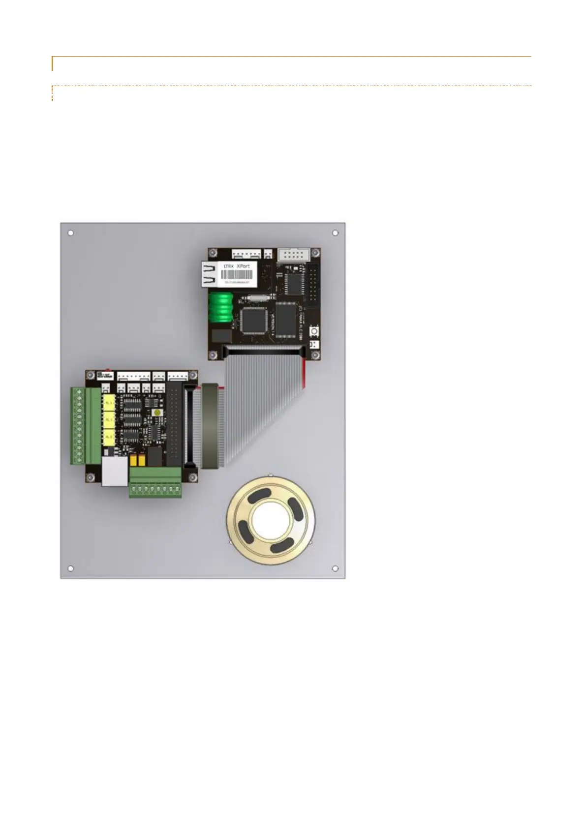
The 16bit Control Board now comes as 2 separate PCB's. There is the main Control PCB that contains the 16bit
processor, LCD & Keypad interfaces, Flash (program memory), SD-RAM (data memory) and Ethernet communications.
There is also an I/O Interface PCB that contains the RS-232 & RS-485 Communications, Reader interfaces, Speaker
interface, Emergency Release interface, 3 x Relay interfaces, PSU interface, Battery interface, Door interfaces and
Receptor interface. The 2 PCB's link together with a short 34 way ribbon cable.
Initially the 2 PCB's will be mounted on a metal bracket which is the same size as the existing 8bit Control PCB. This
will allow the new Control PCB and I/O Interface PCB to be fitted into any existing Traka Pod. In the future we will re-
design the Traka Cabinets and Pods to be smaller.