5.1.2.7 REPLACING THE 16BIT CONTROL PCB
NOTE: Replacing the 16bit Control PCB may take up to half an hour to complete. Please ensure that any
important keys are removed from the systems prior to the replacement, as it may be difficult to obtain the
keys.
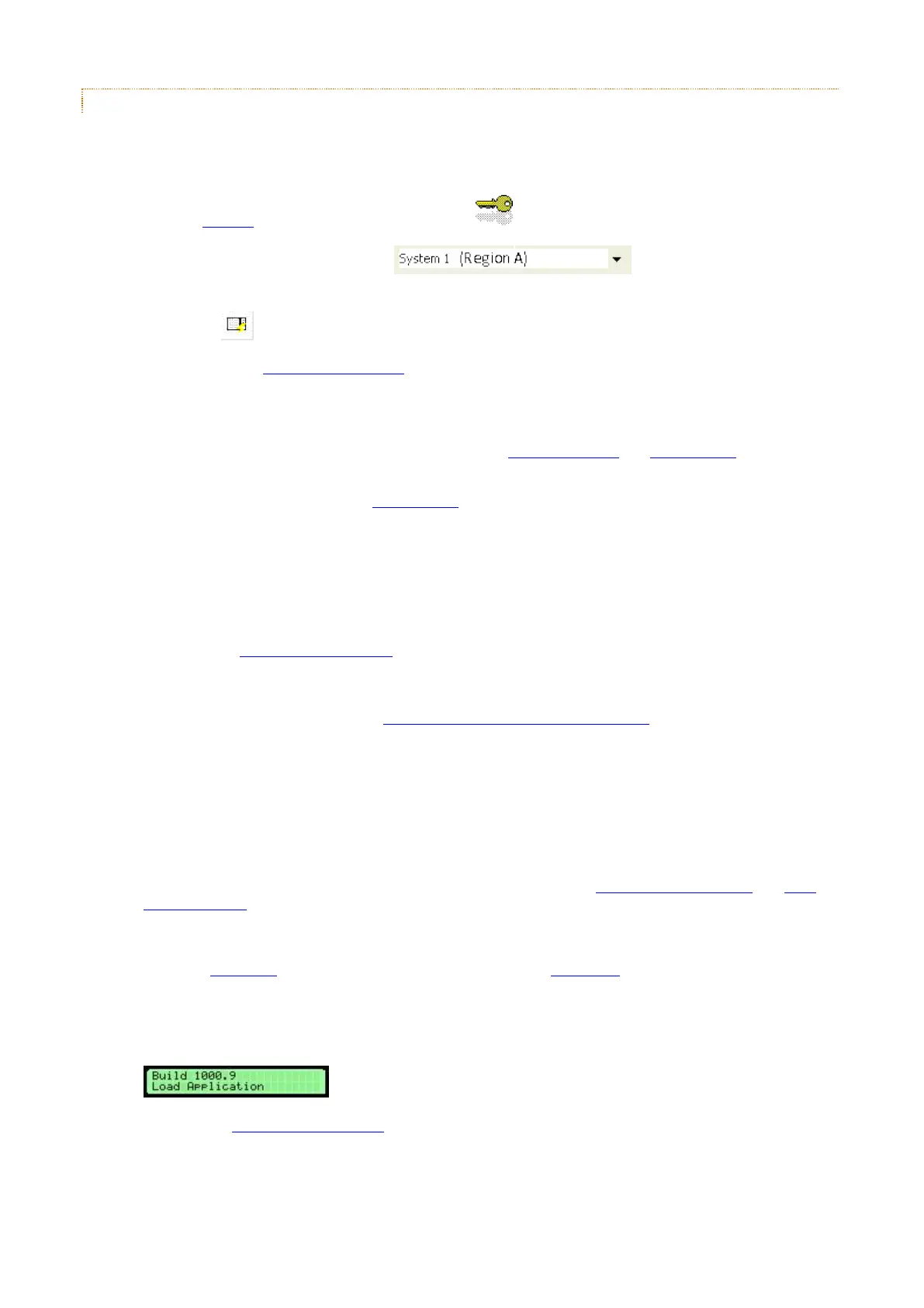
1. Load the Traka32 software by double clicking on the icon.
2. Select the appropriate system from the drop down menu that you wish
to work on.
3. Click on the button.
4. Please refer to the Anti Static Precautions before working on the Traka system.
5. Using the Master Key, unlock the Pod Lock. The Control Panel is hooked in at the bottom and locked at
the top. Carefully begin to remove the Control Panel.
6. You will see that there are several wires connected to the 16bit Control PCB and 16bit I/O PCB that are
attached to the control panel.
7. Set the On/Off switch to OFF on the 16bit I/O PCB.
8. Carefully disconnect any wires from both PCB’s noting where and how they connect and completely remove
the control panel.
9. Place the Control Panel on a suitable flat surface.
10. Remove the four M3 x 12mm hex fixing screws that hold the 16bit Control PCB in place.
11. Check that the Communication Settings are set correctly on the new 16bit Control PCB by copying the
settings from the old 16bit Control PCB. A jumper is required on the top side of the PCB if the XPORT device
is required for Ethernet communications.
12. If not already connected, connect the Secondary Battery Backup Isolator jumper.
NOTE: It is highly recommended that when spare 16bit Control PCB’s are transported or stored
that the Battery Backup Isolator Jumper is removed. This will prolong the life of the battery.
13. Place the new 16bit Control PCB back on the Control Panel and secure with the four fixing screws.
14. Re-connect the short 34 way ribbon cable from the 16bit bit I/O PCB to the 16bit Control PCB.
15. Hook the Control Panel into the bottom of the Pod. Whilst holding the control panel, carefully re-connect
the wires to the 16bit Control PCB and 16bit I/O PCB. Refer to the 16bit Control PCB Layout and 16bit
I/O PCB Layouts for their respective connection diagrams.
16. Set the On/Off switch on the 16bit I/O PCB to On.
17. Check the Power LED comes on and after a few seconds and the Status LED starts to flash. If there is no
Power LED, set the On/Off switch on the 16bit I/O PCB to Off and re-check all of the connections.
NOTE: The status LED should flash when the application firmware is loaded and running. If there
is no application firmware loaded, then the status LED will be solid on and the LCD will show:
In this case a 16 bit firmware upgrade will be required. Contact your distributor for more information.
Because the 16bit firmware is generic, the 16bit Control PCB will usually be supplied with the application
firmware already loaded.