3.19.7.3 FIRE ALARM ACCESS OVERRIDE CONNECTIONS
NOTE: Fire Alarm Access Override is a firmware cost option; please ensure the correct firmware is loaded
prior to using the system.
16bit Systems
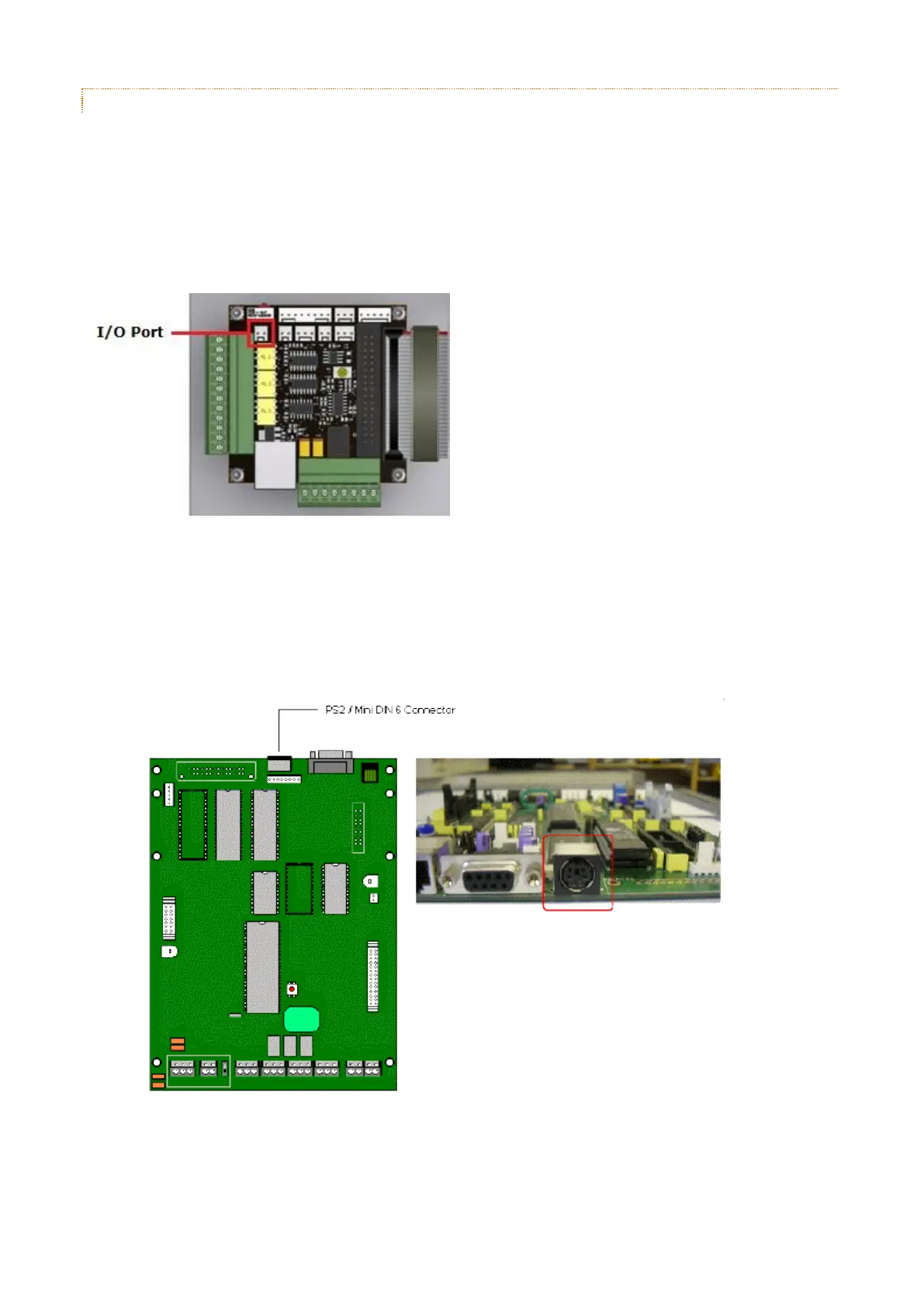
The fire alarm or break glass switch is required to be connected to the I/O Port on the 16bit I/O PCB, located just
behind the On/Off switch as shown below.
8bit Systems
The fire alarm or break glass switch is required to be connected to the PS2 port on the Traka 8-bit Control PCB.
1. The PS2 connector is not fitted as standard therefore if integrating the fire-alarm into an existing Traka
system, a new Control PCB will be required. Alternatively, the connector will need to be soldered onto the
existing 8-bit Control PCB. See below for a diagram of where the PS2 connector is located:
2. A PS2 to Terminal Block Interface Cable is required allowing termination of the fire alarm switch or break
glass switch. The cable can be supplied upon request. See below for a diagram showing the connections
required: