NOTE: This temporary connection will fail quickly, but the device will temporarily change its IP
Address to the one designated.
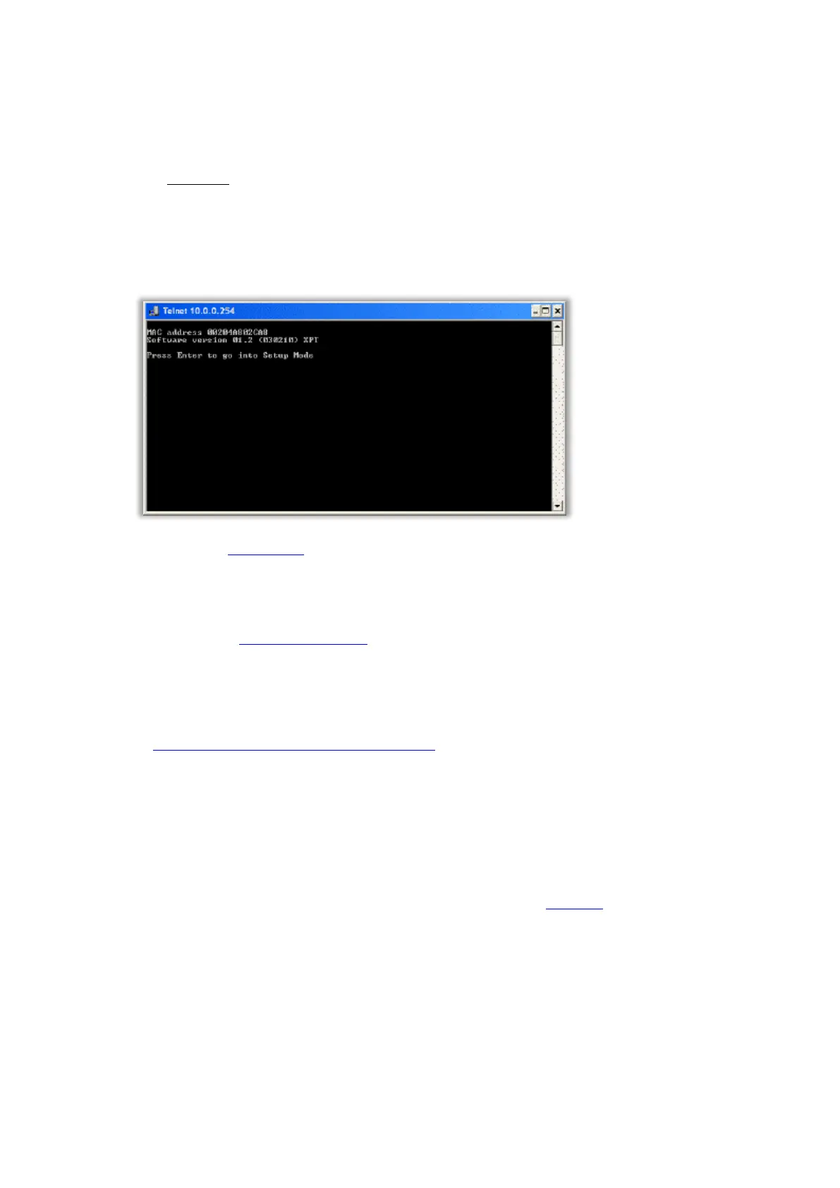
4. Finally we Telnet to the device using port 9999 enabling us to configure. To do this, again click on Start,
Run, type the following and click on OK…
telnet IP-Address 9999
Again, following the above example you would type…
telnet 10.0.0.254 9999
When the following window appears, press Enter quickly to go into the Setup mode…
5. Now refer to the Configuration later in this topic.
Using Traka32 Diagnostics
1. Please refer to the Anti Static Precautions before configuring the Traka systems.
2. Using the Master Key, unlock the Control Panel and tilt forward to gain access to the system electronics.
3. Set the On/Off switch on the Control PCB to Off.
4. If your system is 8bit, ensure the jumper settings are set to Ethernet Config on the Control PCB. Refer to
the 8bit Control PCB Communication Jumper Settings. The 16-bit Control PCB auto-detects the
communications method so no jumper settings are required to be configured.
5. Using an RS232 cable (also know as serial cable) connect the Male End to the RS232 connector on the
Control PCB and the Female End to an available serial port on the chosen PC.
The 8-bit Control PCB has a 9 pin D-Type (female) RS232 connector for connecting the RS232
cable to.
The 16-bit Control PCB is supplied with a short 3 pin Molex to 9-pin D-Type (female) cable for
connecting an RS232 cable to. This connects to UART B on the 16-bit I/O PCB.