4. Depending on your system configuration it's possible that lock cables and RFID cables from adjacent modules
may also be connected to the PCB. If this is the case then these cables must also be disconnected to allow the
module to be freely removed.
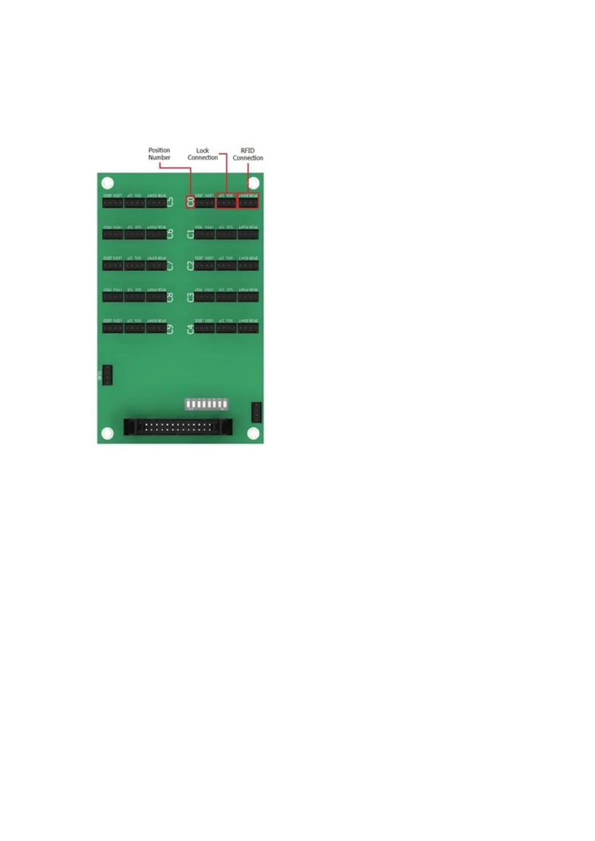
All lock cables and RFID cables are labelled 0-9 according to the position number they connect to on the PCB
(C0-C9). The diagram below shows the location of the lock and RFID cable connectors and the position
number on the PCB.
5. To remove a module that does not have a PCB fixed to the top, follow the lock and RFID cables (if applicable)
to the PCB they are connected to and disconnect. You will also need to disconnect the earth cable as
described in the previous step.
6. Carefully tilt the module forward and lift over the lip at the front of the frame to remove. Take care not to
damage any cables when removing the modules.
NOTE: If your system has been designed with USB charging, depending on the size of your system
it may have a USB Charging PCB fixed to the Locker Frame behind the modules. Each compartment
will have a USB cable connected to the PCB. These must be disconnected in order to remove the
module.
7. Removing all of the modules will expose the wall fixing points in the back of the frame. If your system has the
option of charging in compartments the Power Bars or USB Charging PCBs will also be located in the back of
the frame.


 To Next Page