6. If your system is 8bit, ensure the jumper settings are set to RS232 on the Control PCB. Refer to the 8bit
Control PCB Communication Jumper Settings.
7. Connect the Serial Lead between the Modem Serial Port and the Traka RS232 Port.
8. Connect the Power Lead from the Modem Power Port to the Power Output connector on the Traka Control PCB
or to an external power source depending on the modem type. Refer to the 8bit Control PCB Layout and 16bit
I/O PCB Layout diagrams for details on the available power output connections.
9. Make sure the Modem Power Switch is switched On (Depressed).
10. Switch the On/Off Switch on the Control PCB to On.
11. Hold down the 0 key on the keypad. At the same time press and release the Reset button on the Control
PCB. This will configure the modem with the correct communications settings and to auto answer.
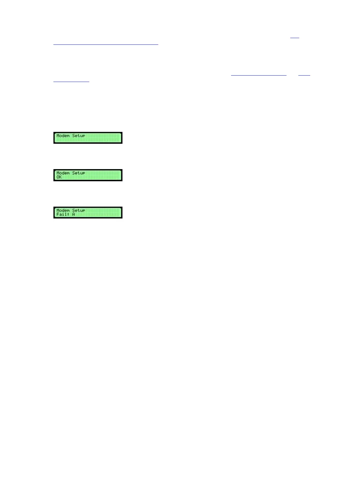
12. When you release the Reset button you should hear two beeps followed by a double beep, this means the
modem is configured successfully.
13. If you hear two beeps followed by an error beep then the modem did not configure correctly, re-check
your connections and try again.
'Fail A' means the modem returned some unexpected data and 'Fail B’ or ’Fail C’ means the modem did not
return anything at all. Check that the modem is connected correctly and power is present and the modem is
switched on.
14. Finally, close the Control Panel carefully and lock with the Master Key.