12 Chapter 2 Flight Safety
Mounts consist of functional module mounts and physical mounts. When adding mounts
to the aircraft, always re-weigh the actual take-off mass of the aircraft.
The mount mass should satisfy: Maximum Mount Mass≤MTOM – Aircraft's Mass.
As the gravity center of the aircraft is located at around the center of the aircraft, it is
recommended that users install mounts as nearly to the center as possible. In this way, the
balance of the aircraft will not be affected usually after installing mounts as long as the
aircraft mass does not exceed MTOM.
Obstacle Avoidance System
Introduction to Visual Sensing System and Millimeter-Wave Radar
Sensing System
The aircraft adopts a dual-sensing system design of "Visual Sensing System + Millimeter-Wave
Radar Sensing System". The integration of these two systems provides excellent omnidirectional
obstacle avoidance performance and ensures precise positioning and safe flight of the aircraft.
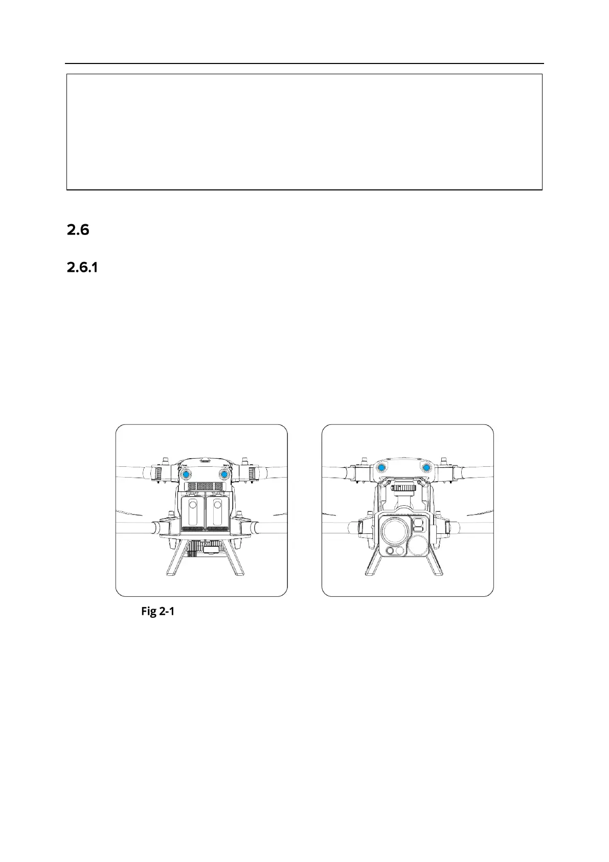
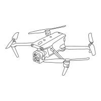
The visual sensing system is an image positioning system that uses visual image ranging to sense
obstacles and obtain aircraft position information. The visual sensing system of the aircraft is
located on the front, rear, upper left, upper right, and bottom of the fuselage. The aircraft uses
a "double fisheye lens" structure to achieve omnidirectional visual obstacle avoidance.
Front and rear visual lens modules of the aircraft