Chapter 3 Aircraft 49
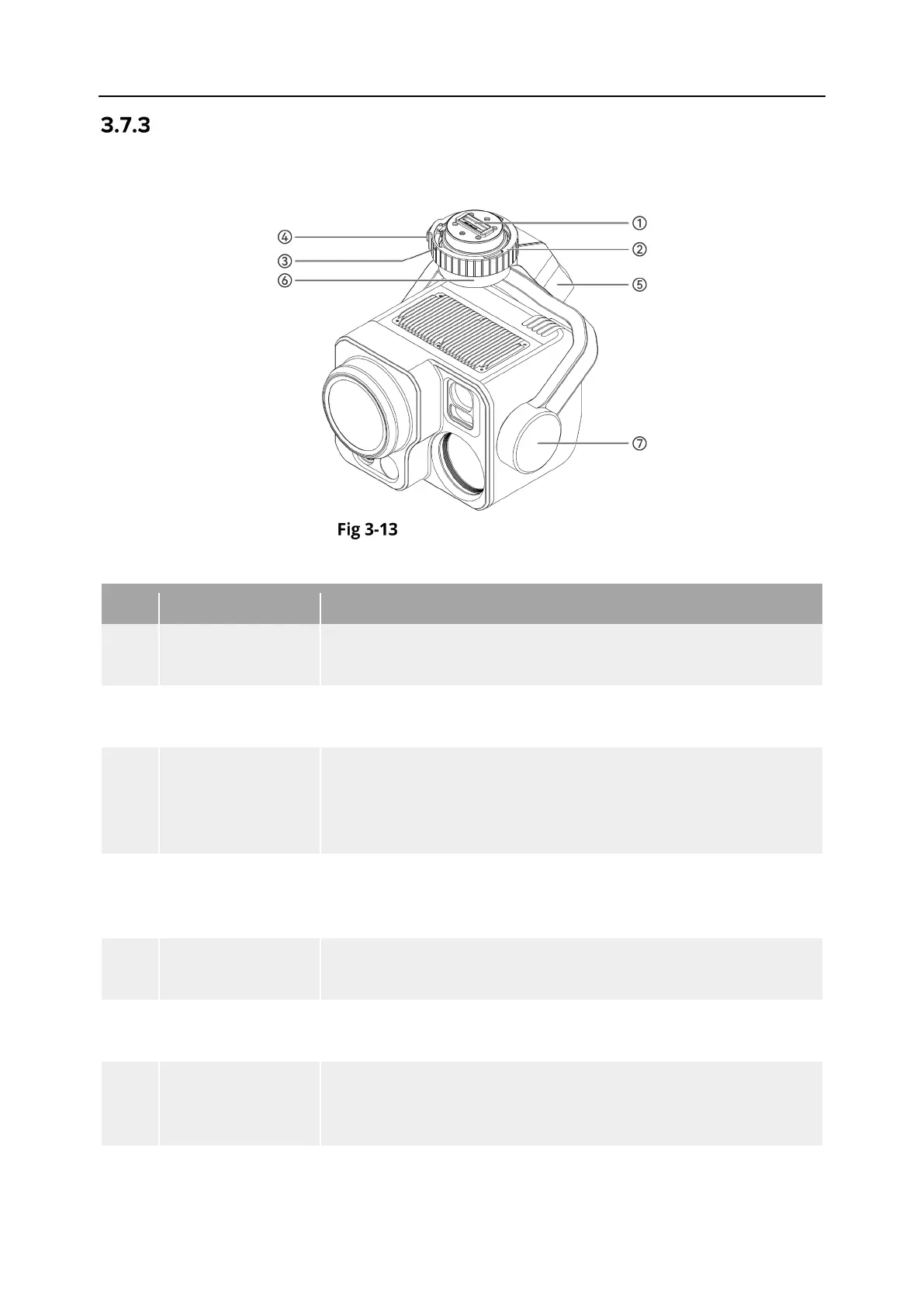
Gimbal Structure
The DG-L35T is equipped with a three-axis stabilized gimbal with a high-precision motor
structure, which can ensure stable camera shooting when the aircraft is flying.
Gimbal Structure
Table 3-10 Gimbal Structure Details
No. Name Description
1 Connection Slot
The gimbal's connection slot is used to connect with the
connector at the aircraft's gimbal interface.
2 Gimbal Lock Ring
The DG-L35T gimbal lock ring features an E-shape design for
quick connection to the aircraft's gimbal interface.
3
Lock Ring Marker
(Red Dot)
Used to check the installation direction of the gimbal lock ring.
When installing the gimbal, rotate the marker point from
aligning with the unlock indicator on the aircraft's gimbal
interface to the lock indicator.
4
Gimbal lock
Button
When installing or removing the gimbal camera, press and hold
the gimbal lock button to ensure that the gimbal lock ring is
5 Roll Axis Motor
Used to control the moving range of the gimbal to roll left or
right (mechanical range: -60° ~ +60°).
6 Yaw Axis Motor
Used to control the moving range of the gimbal to rotate left or
right with its own axis (mechanical range: -90° ~ +90°).
7 Pitch Axis Motor
Used to control the moving range of the gimbal to rotate up or
down (mechanical range: -135° ~ +45°, controllable movement